
Composite electronic component and board having the same

a technology of electronic components and composites, applied in the direction of fixed capacitor details, printed circuit non-printed electric components association, final product manufacture, etc., can solve the problems of vibration, listener discomfort, acoustic noise, etc., and achieve the effect of reducing acoustic nois

Active Publication Date: 2016-05-12
SAMSUNG ELECTRO MECHANICS CO LTD
View PDF10 Cites 47 Cited by
  • Summary
  • Abstract
  • Description
  • Claims
  • Application Information

AI Technical Summary

Benefits of technology

This patent is about a new type of electronic component that can reduce acoustic noise. This invention is aimed at reducing the noise generated by electronic components in devices like computers and televisions. The patent's technical effect is to provide a way to make electronic components quieter and more efficient. This invention can be used in circuits and packaging units for these components.

Problems solved by technology

Since the dielectric layers have piezoelectric and electrostrictive properties, a piezoelectric phenomenon occurs between the internal electrodes when a direct current (DC) voltage or alternating current (AC) voltage is applied to the multilayer ceramic capacitor, and thus vibrations may be generated.
The vibration sound may be within an audio frequency range of 20 to 20,000 Hz, which may cause listener discomfort and is referred to as acoustic noise.
In accordance with the recent trend toward compactness and slimness of electronic devices, multilayer ceramic capacitors have been used together with printed circuit boards in environments in which high voltages are used and changes in voltage frequently occur, and thus, levels of acoustic noise may be increased so that the acoustic noise may be audible to users.

Method used


Image

  • Composite electronic component and board having the same
  • Composite electronic component and board having the same
  • Composite electronic component and board having the same

Examples


Embodiment Construction

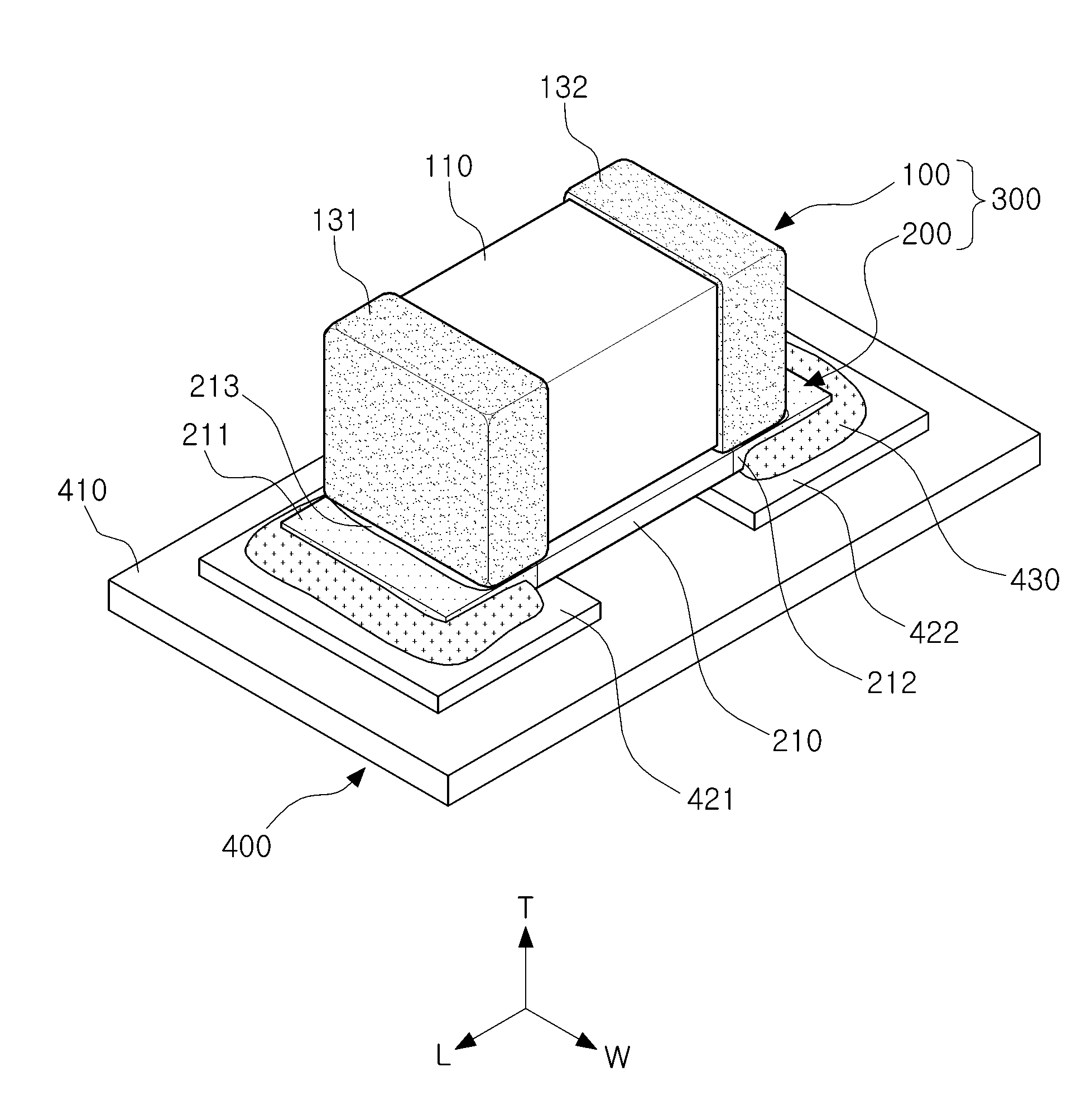
[0044]Hereinafter, embodiments of the present disclosure will be described in detail with reference to the accompanying drawings. The disclosure may, however, be embodied in many different forms and should not be construed as being limited to the embodiments set forth herein. Rather, these embodiments are provided so that this disclosure will be thorough and complete, and will fully convey the scope of the disclosure to those skilled in the art. In the drawings, the shapes and dimensions of elements may be exaggerated for clarity, and the same reference numerals will be used throughout to designate the same or like elements.

Composite Electronic Component

[0045]FIG. 1 is a perspective view schematically illustrating a composite electronic component according to an exemplary embodiment.

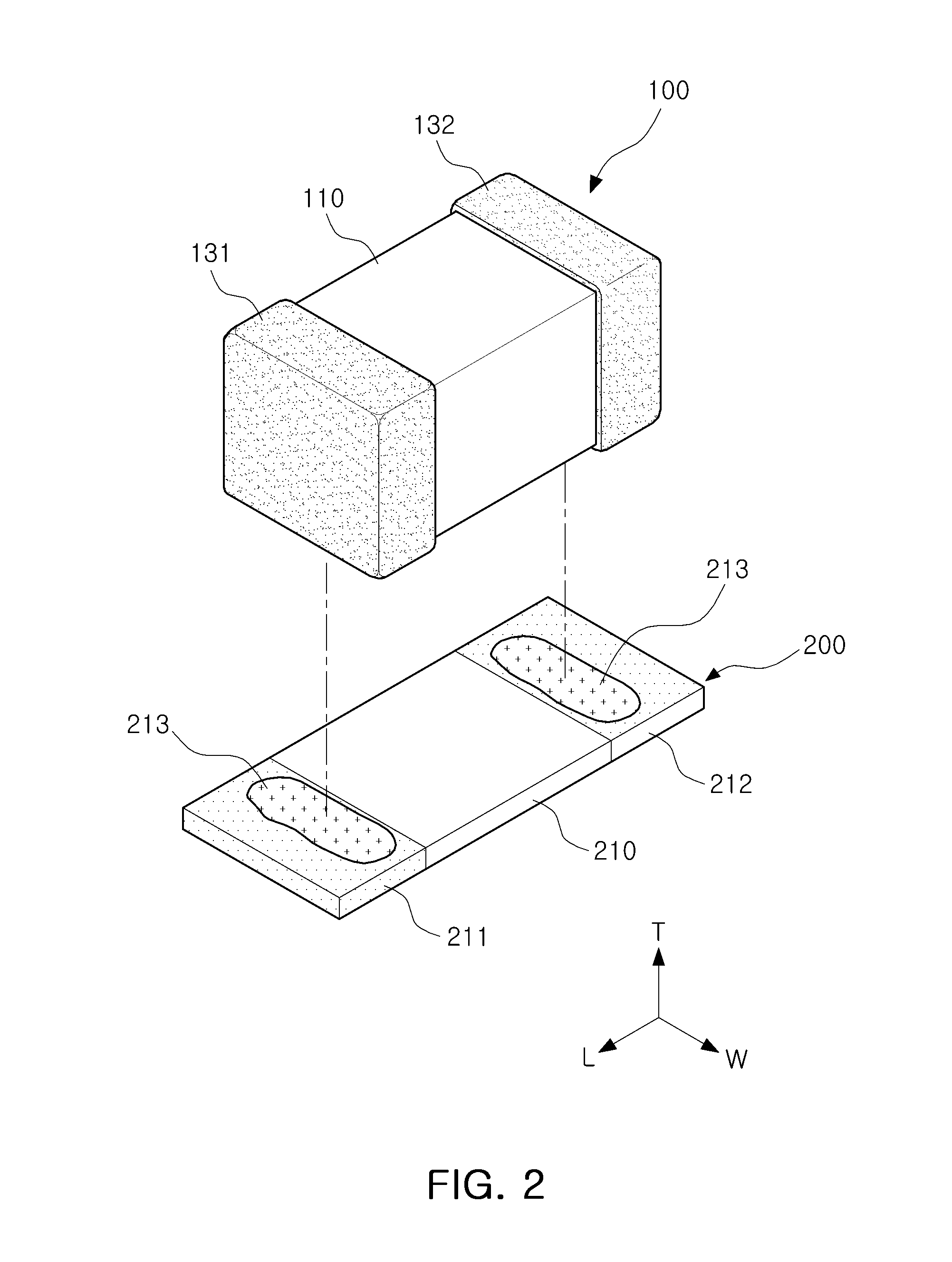
[0046]FIG. 2 is an exploded perspective view illustrating a multilayer ceramic capacitor and a ceramic electronic component of the composite electronic component of FIG. 1.

[0047]With respect to direction...


PUM

PropertyMeasurementUnit
Lengthaaaaaaaaaa
Electrical conductoraaaaaaaaaa

Abstract

A composite electronic component includes a composite body in which a multilayer ceramic capacitor and a ceramic electronic component are coupled to each other. The multilayer ceramic capacitor includes a first ceramic body comprising dielectric layers and internal electrodes, the internal electrodes having at least one of the dielectric layers interposed therebetween; and first and second external electrodes disposed on first and second end portions of the first ceramic body. The ceramic electronic component includes a second ceramic body coupled to a lower portion of the multilayer ceramic capacitor and made of ceramic; and first and second terminal electrodes disposed on first and second end portions of the second ceramic body and connected to the first and second external electrodes, and the multilayer ceramic capacitor and the ceramic electronic component have different lengths.

Description

CROSS-REFERENCE TO RELATED APPLICATION[0001]This application claims the benefit of priority to Korean Patent Application No. 10-2014-0155179, filed on Nov. 10, 2014 with the Korean Intellectual Property Office, the entirety of which is incorporated herein by reference.BACKGROUND[0002]The present disclosure relates to a composite electronic component, a board having the same, and a packing unit therefor.[0003]A multilayer ceramic capacitor (MLCC), a multilayer electronic component, is a type of capacitor mounted on the printed circuit boards of various electronic products including display devices such as liquid crystal displays (LCDs) and plasma display panels (PDPs), computers, smartphones, mobile phones, and the like, to serve to charge and discharge electricity therein.[0004]Since a multilayer ceramic capacitor has advantages such as small size, high capacitance, and ease of mounting, it may be used as a component in various electronic devices.[0005]The multilayer ceramic capacit...

Claims


Application Information

Patent Timeline
IPC IPC(8): H01G4/40H05K1/18H01G4/30
CPCH01G4/40H05K1/181H01G4/30H01G2/06H01G4/12H01G4/228H05K3/301H05K3/321H05K3/3431H05K3/3442H05K2201/10015H05K2201/10636H05K2201/10651H05K2201/2045H05K2203/0465Y02P70/50
Inventor PARK, SANG SOOJUN, KYOUNG JINAHN, YOUNG GHYUPARK, HEUNG KIL
Owner SAMSUNG ELECTRO MECHANICS CO LTD
Learn More