
Photoacoustic remote sensing (PARS)

a remote sensing and photoacoustic technology, applied in the field of biomedical optics imaging, can solve the problems of inability to achieve the desired effect,

Active Publication Date: 2016-04-28
ILLUMISONICS INC
View PDF8 Cites 91 Cited by
  • Summary
  • Abstract
  • Description
  • Claims
  • Application Information

AI Technical Summary

Benefits of technology

The patent describes a photoacoustic remote sensing system (PARS) for imaging a subsurface structure in a sample. The system includes an excitation beam, an interrogation beam, an optical system, an interferometer, and an endoscopic device. The excitation beam generates ultrasonic signals in the sample, while the interrogation beam detects the signals. The system can create an image of the sample by detecting the returning portion of the interrogation beam. The technical effects of the patent include improved imaging of subsurface structures in samples and the use of a fiber optic cable for efficient detection of ultrasonic signals.

Problems solved by technology

In OR-PAM, penetration depth is limited to ˜1 mm in tissue (due to fundamental limitations of light transport) but resolution is micron-scale due to optical focusing.
Much can go wrong at the capillary level too.
However, for many clinical applications such as wound healing, burn diagnostics, surgery, and many endoscopic procedures physical contact, coupling, or immersion is undesirable or impractical.
Optical means of detecting ultrasound and photoacoustic signals have been investigated over a number of years; however, to date no technique has demonstrated practical non-contact in vivo microscopy in reflection mode with confocal resolution and optical absorption as the contrast mechanism.
However, these systems suffer from a poor signal-to-noise ratio, other contact-based photoacoustic systems offer significantly improved detection capabilities, in vivo imaging was not demonstrated, and optical-resolution excitation was not demonstrated.
This approach has been adapted to detect ultrasound ex vivo in chicken breast and calf brain specimens, however, optical-resolution focusing of the excitation light was not examined.
Laser Doppler vibrometry has been a powerful non-contact vibration sensing methodology, however, weak signal-to-noise and poor image quality have proven to be a limitation when sensing deep-tissue signals from broad-beam photoacoustic excitation.
However, many such techniques still require direct contact or fluid coupling and have not offered in vivo studies or optical resolution for phantom studies.

Method used


Image

  • Photoacoustic remote sensing (PARS)
  • Photoacoustic remote sensing (PARS)
  • Photoacoustic remote sensing (PARS)

Examples


Embodiment Construction

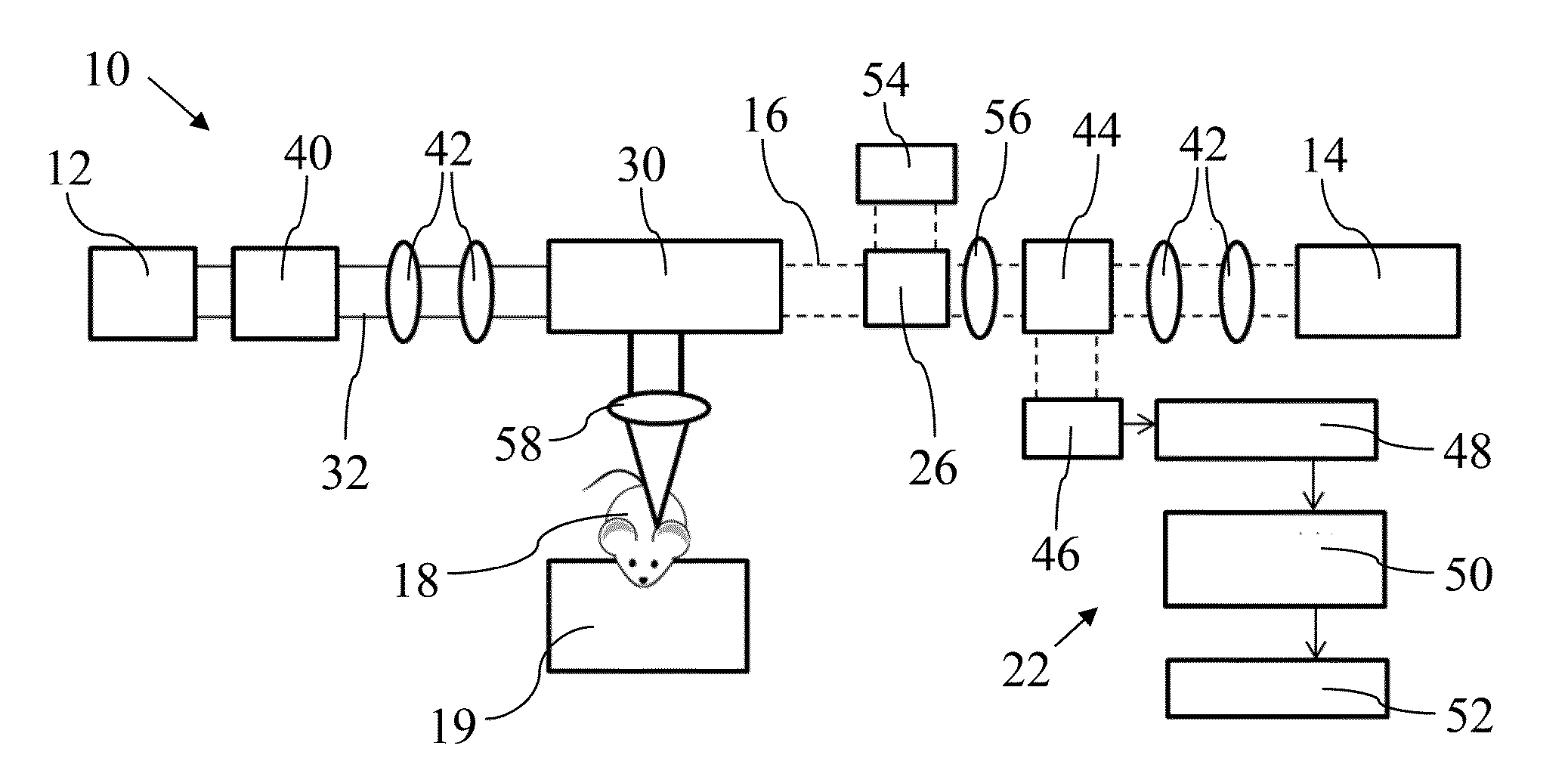
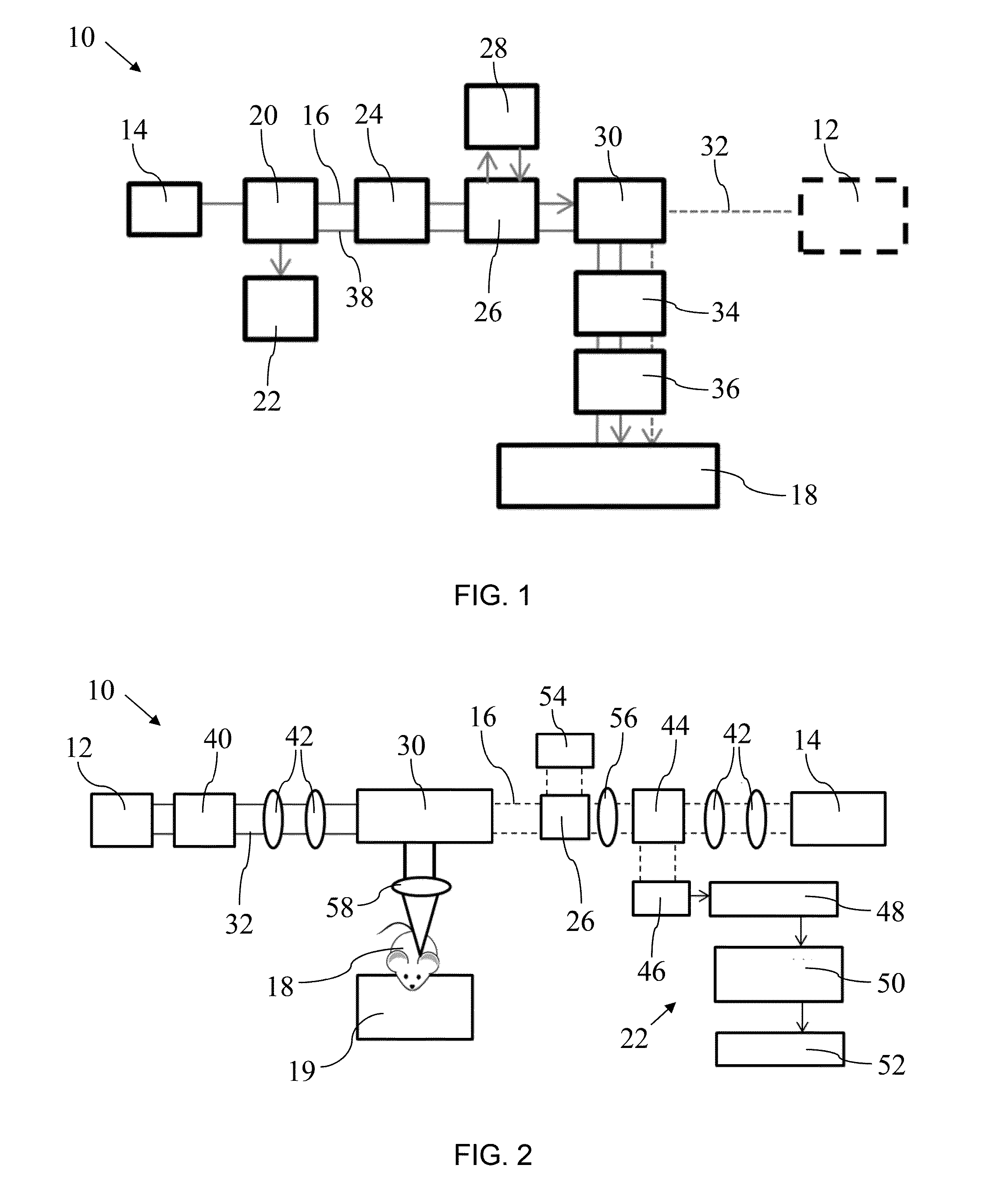
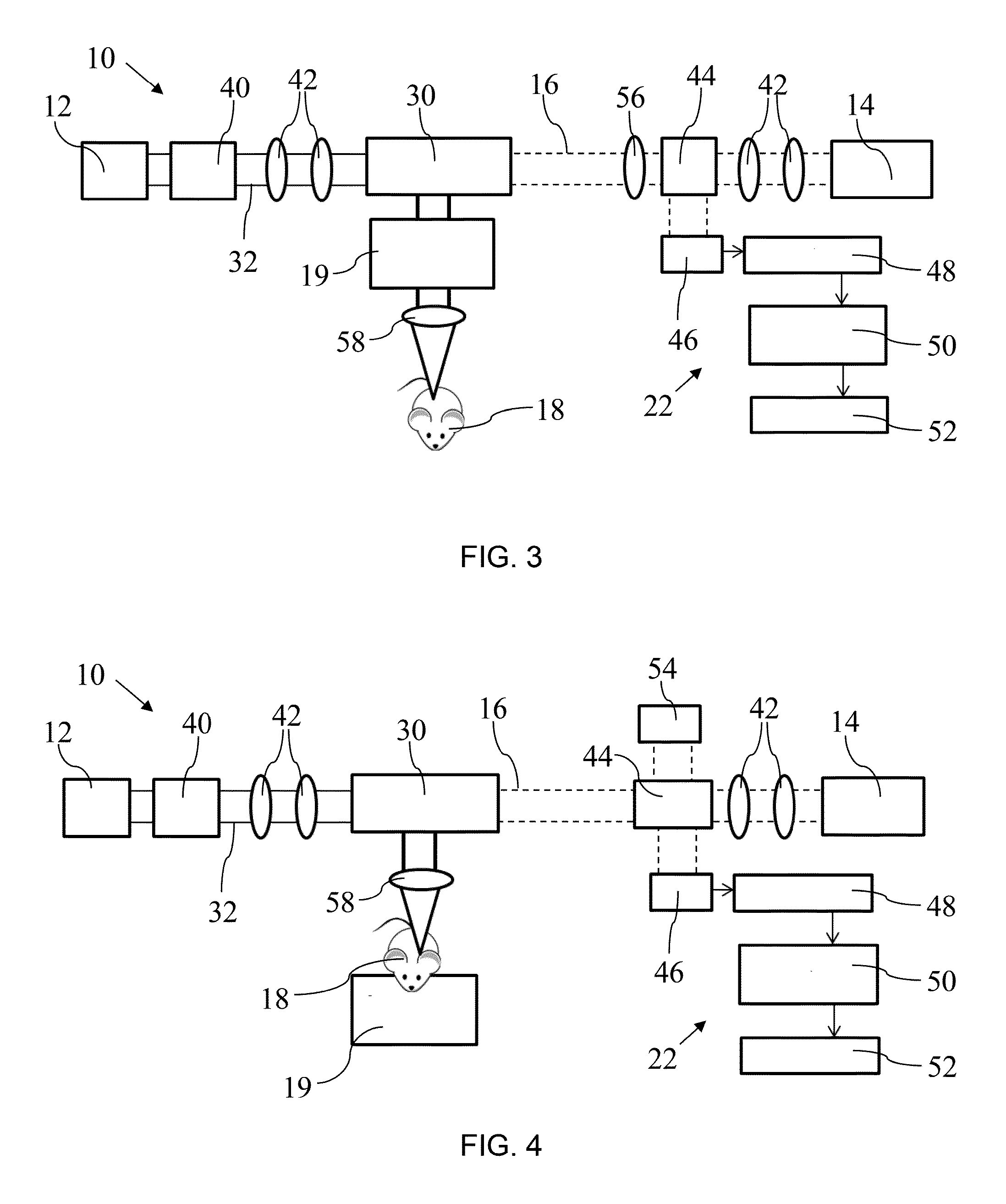
[0046]Photoacoustic imaging is an emerging biomedical imaging modality that uses laser light to excite tissues. Energy absorbed by chromophores or any other absorber is converted to acoustic waves due to thermo-elastic expansion. These acoustic signals are detected and reconstructed to form images with optical absorption contrast. Photoacoustic (PA) imaging has been shown to provide exquisite images of microvessels and is capable of imaging blood oxygen saturation, gene expression, and contrast agents, among other uses. In most PA and ultrasound imaging systems, piezoelectric transducers have been employed, in which an ultrasound coupling medium such as water or ultrasound gel is required. However, for many clinical applications such as wound healing, burn diagnostics, surgery, and many endoscopic procedures physical contact, coupling, or immersion is undesirable or impractical. The system described herein is capable of in vivo optical-resolution photoacoustic microscopy using non-c...


PUM


Abstract

A photoacoustic remote sensing system (PARS) for imaging a subsurface structure in a sample has an excitation beam configured to generate ultrasonic signals in the sample at an excitation location; an interrogation beam incident on the sample at the excitation location, a portion of the interrogation beam returning from the sample that is indicative of the generated ultrasonic signals; an optical system that focuses at least one of the excitation beam and the interrogation beam with a focal point that is below the surface of the sample; and a detector that detects the returning portion of the interrogation beam.

Description

BACKGROUND[0001]1. Technical Field[0002]This relates to the field of biomedical optics imaging and, in particular, to a laser and ultrasound-based method and system for in vivo or ex vivo, non-contact imaging of biological tissue.[0003]2. Description of the Related Art[0004]Photoacoustic imaging is an emerging hybrid imaging technology providing optical contrast with high spatial resolution. Nanosecond or picosecond laser pulses fired into tissue launch thermo-elastic-induced acoustic waves which are detected and reconstructed to form high-resolution images. Photoacoustic imaging has been developed into multiple embodiments, including photoacoustic tomography (PAT), photoacoustic microscopy (PAM), optical-resolution photoacoustic microscopy (OR-PAM), and array-based PA imaging (array-PAI). In photoacoustic tomography (PAT) signals are collected from multiple transducer locations and reconstructed to form a tomographic image in a way similar to X-ray CT. In PAM, typically, a single e...

Claims


Application Information

Patent Timeline
IPC IPC(8): A61B5/00G01N21/17
CPCA61B5/0095G01N21/1702G01N2201/06113G01N2201/08G01N2021/1706G01N2201/0846G01N21/1717G01N2021/1725
Inventor REZA, PARSIN HAJIZEMP, ROGER
Owner ILLUMISONICS INC
Learn More