
Integrated X-ray source having a multilayer total internal reflection optic device

a technology of optic devices and integrated x-ray sources, applied in x-ray tubes, nanoinformatics, nuclear engineering, etc., can solve the problems of drifting of x-ray beam generation points, inability to arrange, and inability to align optics and x-ray generation points

Inactive Publication Date: 2014-06-03
BAKER HUGHES HLDG LLC
View PDF27 Cites 29 Cited by
  • Summary
  • Abstract
  • Description
  • Claims
  • Application Information

AI Technical Summary

Problems solved by technology

Additional issues with respect to an X-ray source point and optics arrangement include: alignment of the optics and the X-ray generation point, and drifting of the X-ray beam generation point due to target heating or lack of dynamic electron beam control.
The optimal position for disposing the optic to obtain maximum X-ray intensity would be at the X-ray generation point, however, with commercially available optics such as polycapillary optics or the singly- or doubly-curved diffractive optics such an arrangement is not feasible.
This large distance between the optics and the X-ray generation point reduces the intensity of the output X-ray beam that comes out of the optics.
For both singly and / or doubly curved diffractive optics, the optics are typically placed at distances on the order of centimeters from the X-ray generation point to reduce the strain in the optics, which makes the optics difficult to manufacture and reduces the optic output beam quality.
In addition to reducing the X-ray intensity, placing the optic at a large distance away from the X-ray generation point also reduces the robustness of the optic alignment with the X-ray generation point.
Lastly, polycapillary optics are limited to transmitting X rays below 60 keV, which prevents them from being used in a number of non-destructive testing (NDT) imaging applications, e.g. computed tomography (CT) of electronic circuit boards.

Method used


Image

  • Integrated X-ray source having a multilayer total internal reflection optic device
  • Integrated X-ray source having a multilayer total internal reflection optic device
  • Integrated X-ray source having a multilayer total internal reflection optic device

Examples


Embodiment Construction

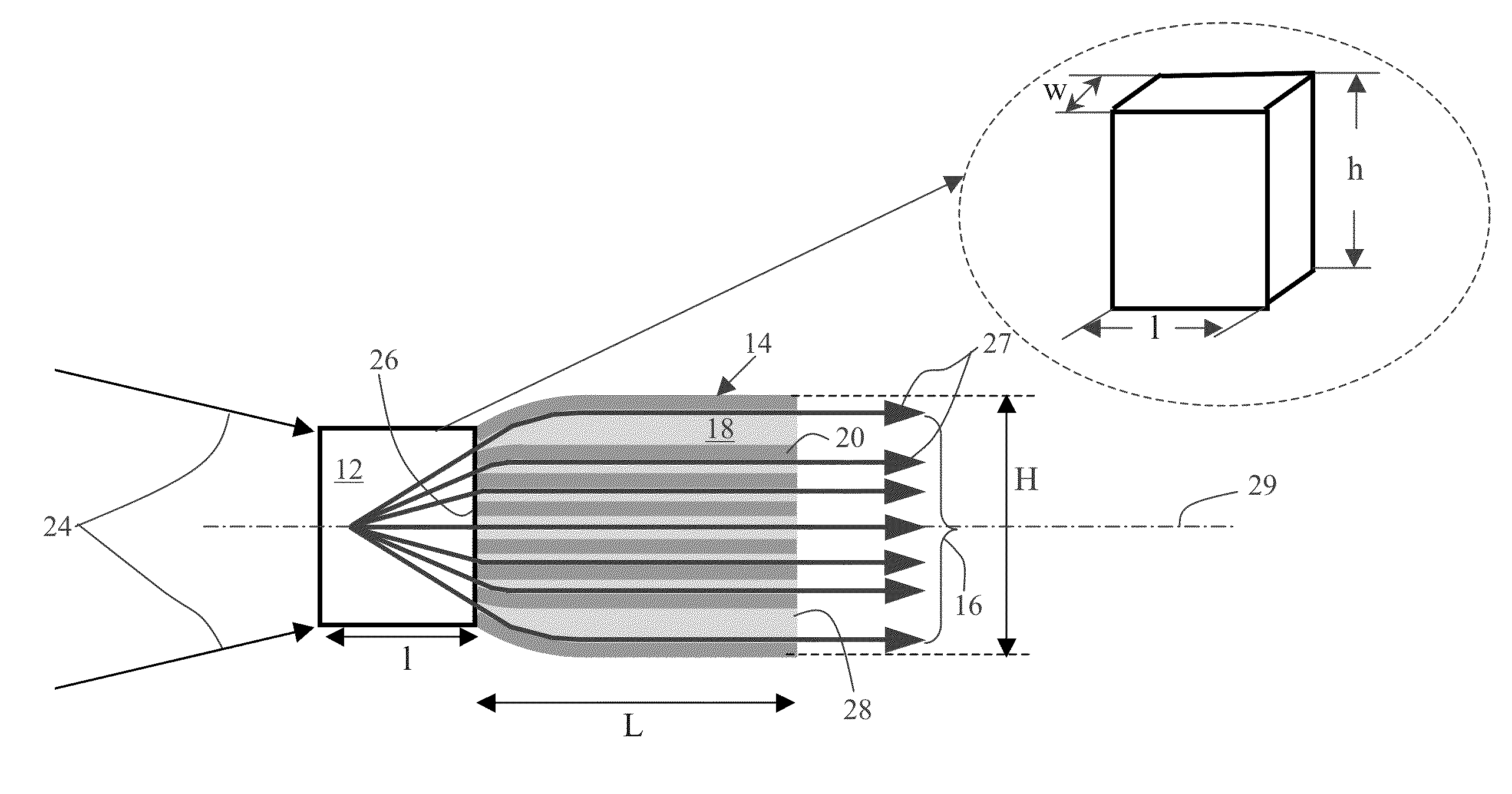
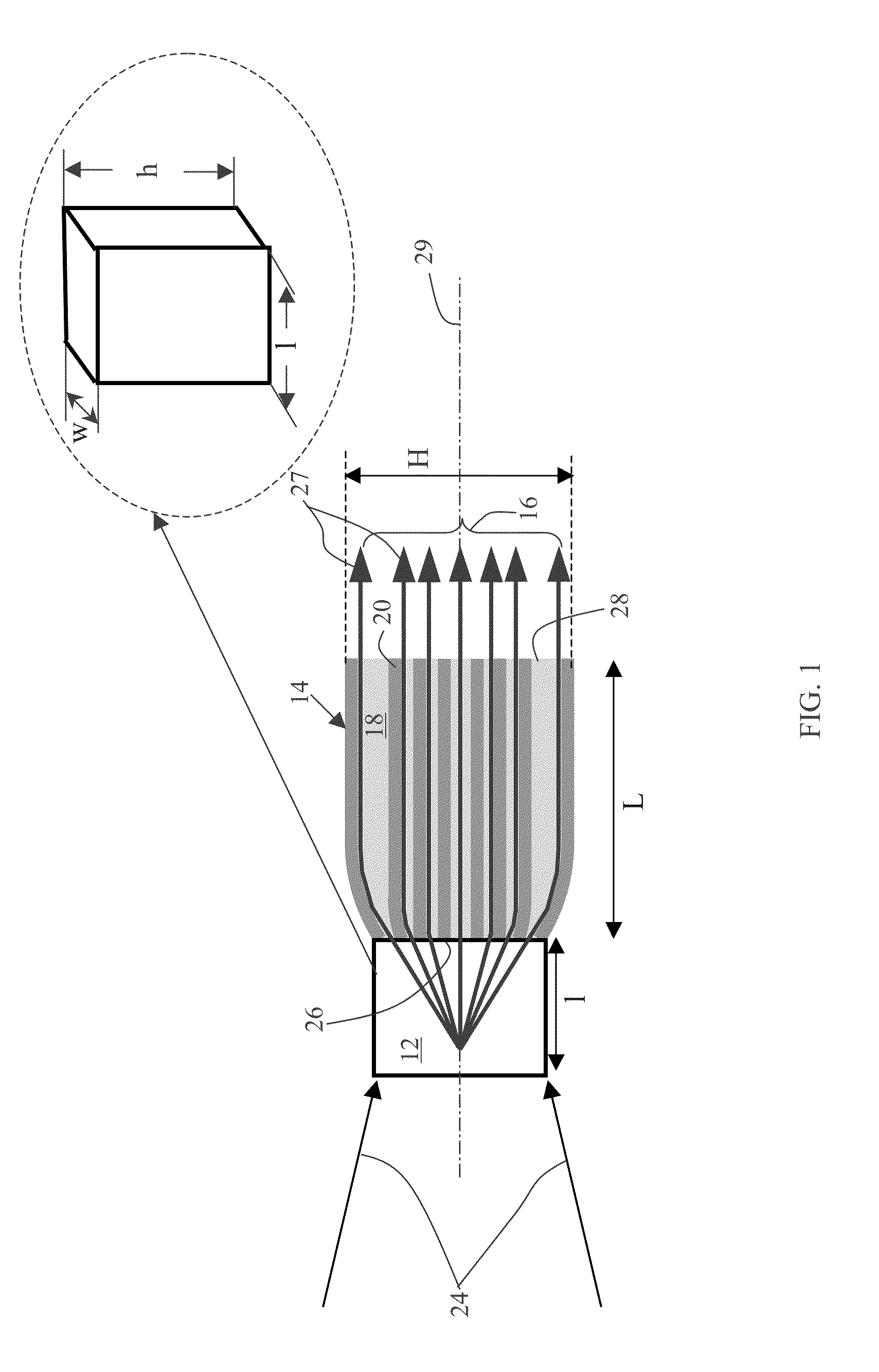
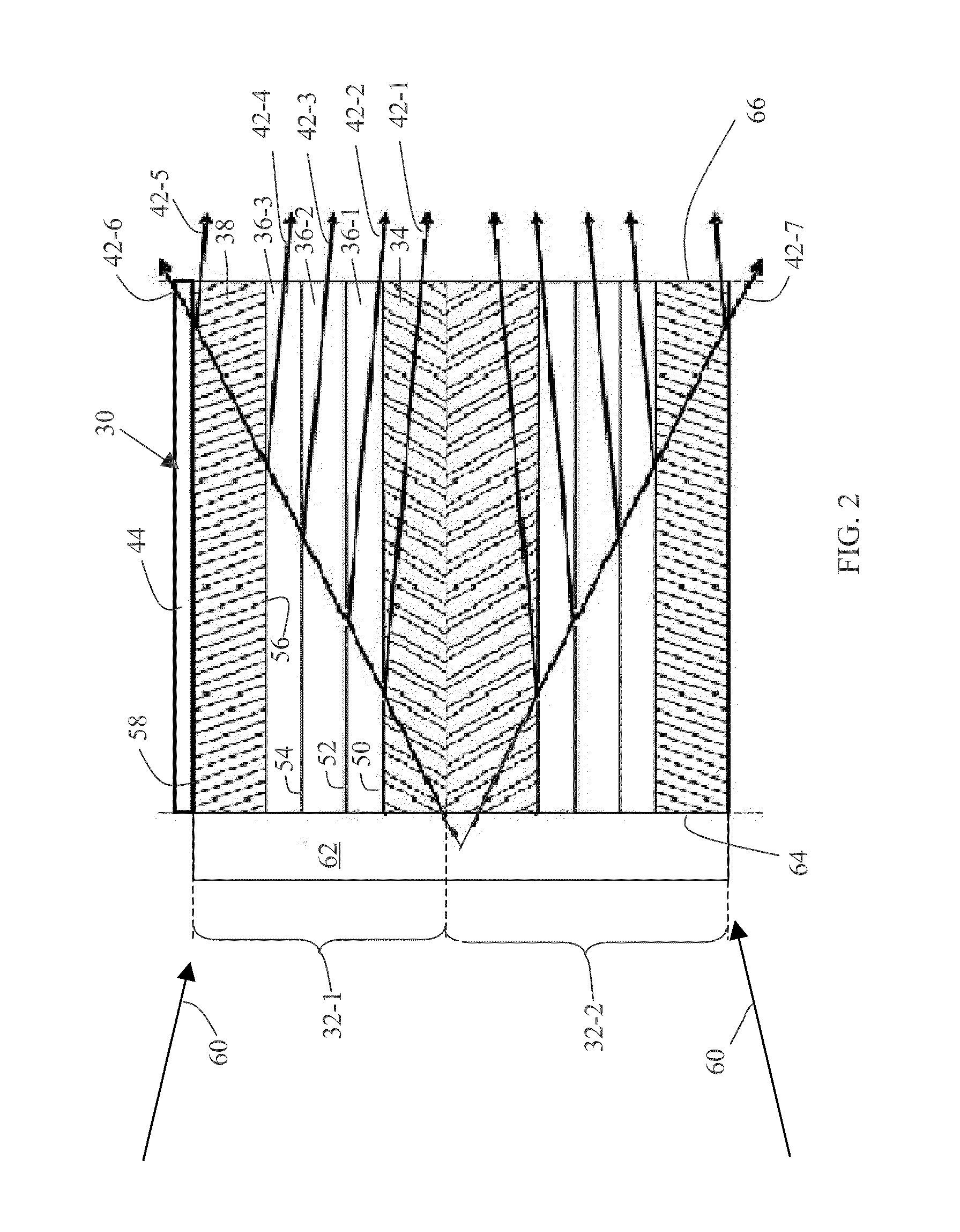
[0013]Embodiments of the system relate to an integrated X-ray source having a target disposed in physical contact with one or more total internal reflection multilayer optic devices. The integrated X-ray source is configured to generate X rays and redirect the generated X rays via total internal reflection to produce X rays having desired beam shapes. The X-ray beams may include fan-shaped beams, beams with circularly symmetric cross-sections, or beams with elliptical cross-sections. Advantageously, the system enables greater X-ray flux output, and a more compact and robust design of the X-ray source.

[0014]The optic device may include an input face and an output face. The input face may be defined as the face of the optic device that is closer to the incident excitation source, and the output face may be defined as the face through which the redirected X-ray beams exit the optic device of the integrated X-ray source. In one embodiment, the input face may be the face of the optic dev...


PUM


Abstract

An integrated X-ray source is provided. The integrated X-ray source includes a target for emitting X-rays upon being struck by one or more excitation beams, and one or more total internal reflection multilayer optic devices in physical contact with the target to transmit at least a portion of the X rays through total internal reflection to produce X-ray beams, wherein the optic device comprises an input face for receiving the X rays and an output face through which the X-ray beams exit the integrated X-ray source.

Description

BACKGROUND[0001]This disclosure relates to X-ray imaging systems, and, in particular, to X-ray imaging systems employing optic devices to produce X-ray beams having desired spectral shape and properties.[0002]Conventional laboratory sources produce a large cone of X rays, the majority of which typically are not utilized to analyze a sample in an X-ray system. X-ray optics may be used to redirect some of these unused X rays into useful directions. However, the efficiency of redirection decreases with increasing distance between the X-ray generation point inside the X-ray source and the collecting / redirecting optic(s). This decrease is typically due to the decrease in X-ray intensity with increasing distance between the X-ray generation point and the optics. Specifically, the X-ray intensity decreases as the square of the distance between the optics and X-ray generation point. Additional issues with respect to an X-ray source point and optics arrangement include: alignment of the opti...

Claims


Application Information

Patent Timeline
Patent Type & Authority Patents(United States)
IPC IPC(8): H01J35/18G21K1/00G21G4/04H01J35/08
CPCH01J35/08G21K1/062B82Y10/00
Inventor LEE, SUSANNE MADELINEEDIC, PETER MICHAELHOPKINS, FORREST FRANKHAASE, ALFRIEDNEUSER, EBERHARD
Owner BAKER HUGHES HLDG LLC
Learn More