Electric vehicle shielded power cable connector
a technology for shielded power cables and electric vehicles, which is applied in the direction of coupling device connections, electrical equipment, coupling protection earth/shielding arrangements, etc., can solve the problems of reducing the efficiency of the electric system, resisting heating, and damage to adjacent parts
- Summary
- Abstract
- Description
- Claims
- Application Information
AI Technical Summary
Benefits of technology
Problems solved by technology
Method used
Image
Examples
first embodiment
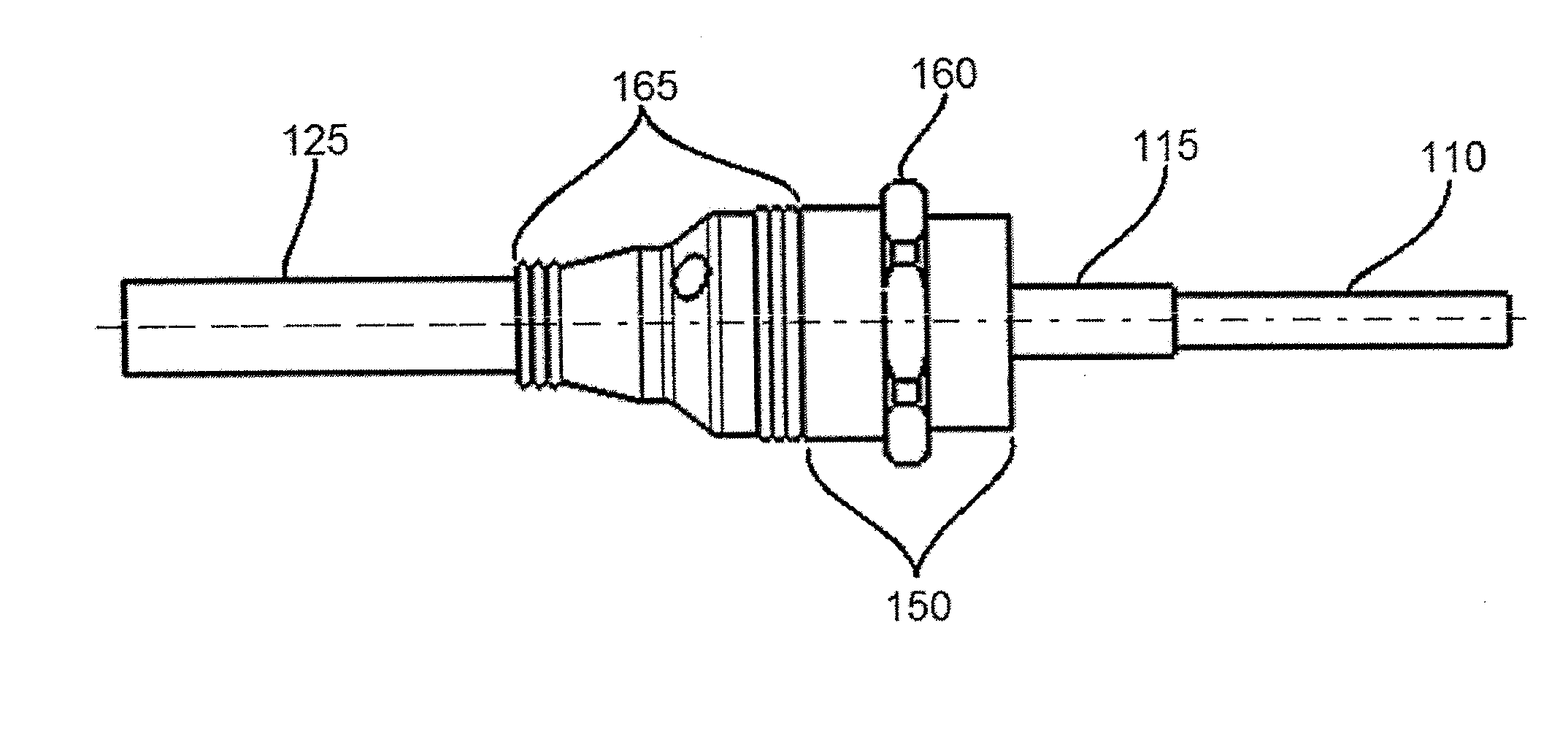
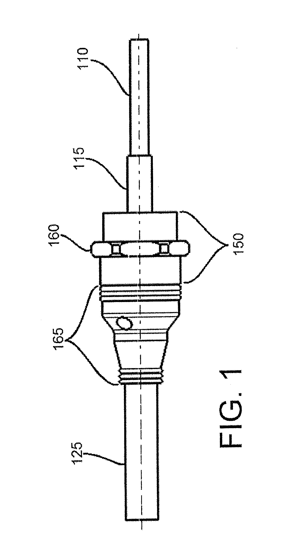
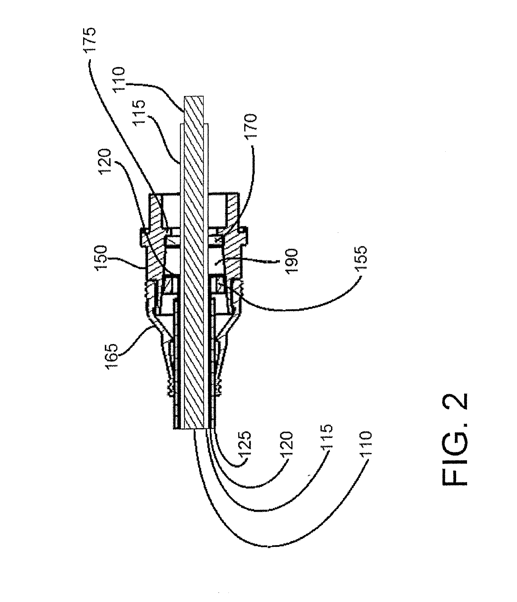
[0035]FIG. 1 illustrates a shielded cable having a connection end prepared for connection to a termination point and the connector of the present invention assembled therewith. Connector body 150 includes mounting feature 160 for mechanically attaching the connection end of the connector to a termination point. The connector in FIG. 1 further comprises flexible boot 165 positioned over a cable end of connector body 150.
[0036]Flexible boot 165 extends from the cable end of connector body 150 onto the shielded cable outer insulator 125. The flexible boot 165 includes constrictive ridges on both ends to provide an environmental seal to the external surfaces of the cable end of connector body 150 and the outer insulator 125. The exterior of flexible boot 165 tapers from a diameter large enough to snugly fit over the cable end of connector body 150 to a smaller diameter providing a seal around the outer insulator 125. Flexible boot 165 is optionally but preferably provided to prevent flu...
second embodiment
[0051]In an illustration of the present invention, FIG. 4 shows that an adhesive 200 may be provided where the flexible braided shield sheath 120 is compressed between the tapered compression ring 155 and the hollow interior surface of the connector body 150. This embodiment of the present invention increases the mechanical strength (i.e., ruggedizes) of the connector assembly created by the self-locking tapered surfaces of the connector body 150 and tapered compression ring 155. The adhesive 200 used in this embodiment may be an epoxy or other strong securing medium. In an exemplary embodiment, the adhesive 200 is capable of exposure to high heat when set and is of a low viscosity when applied such that there is capillary penetration to fill, partially or completely, the interstitial spaces between the braided shield wires of sheath 120 in the region where they are compressed. The adhesive 200 may be provided to some or all of the compressed area of sheath 120.
[0052]FIG. 5 provides...
embodiment 3
[0053]A benefit of the adhesive 200 applied to the braided sheath 120, in FIG. 4, is protection against galvanic corrosion due to the electrochemical potential between the dissimilar metals of the braided sheath and the connector body. With the addition of the adhesive 200, it can be seen that the critical junction between the cable shield 120 and the connector body is encapsulated in a protective resin in This prevents any corrosion that can be precipitated by the presence of dissimilar metals in contact with one another. In an embodiment that includes both the adhesive 200 of FIG. 4 and the adhesive sealer 310 of FIG. 5, the adhesive sealer 310 further protects the metals at the junction from harsh environmental conditions that would promote corrosion.
[0054]A further benefit that the sealing adhesive 310 provides is an improvement over prior art connectors in which shield wires harden from vibration, break free, and can then migrate to some point where a short circuit can occur. ...
PUM
 Abstract
Description
Claims
Application Information
 - R&D
- Intellectual Property
- Life Sciences
- Materials
- Tech Scout
- Unparalleled Data Quality
- Higher Quality Content
- 60% Fewer Hallucinations
Browse by: Latest US Patents, China's latest patents, Technical Efficacy Thesaurus, Application Domain, Technology Topic, Popular Technical Reports.
© 2025 PatSnap. All rights reserved.Legal|Privacy policy|Modern Slavery Act Transparency Statement|Sitemap|About US| Contact US: help@patsnap.com


