
Production method for fine metal particles, production method for fuel cell electrode catalyst, supported fine metal particle catalyst, and fuel cell electrode catalyst

a production method and technology for fuel cells, applied in cell components, active material electrodes, transportation and packaging, etc., can solve the problems of complex process, unhomogeneous catalyst particle diameter, and inability to meet the requirements of production, so as to reduce the cost of raw materials, reduce the effect of reaction and reduce the manufacturing cos

Active Publication Date: 2016-03-24
UNIVERSITY OF YAMANASHI
View PDF2 Cites 11 Cited by
  • Summary
  • Abstract
  • Description
  • Claims
  • Application Information

AI Technical Summary

Benefits of technology

The patent describes a complicated and time-consuming process for making a special catalyst with high dispersion of platinum particles. The method involves coating the catalyst particles with a layers of platinum using a nanocapsule solution containing a precursor. The process involves several steps and requires a long time. The patent also suggests a method to increase the coating layer of the noble metal by hydrogen bubbling. The technical effects of the patent are to provide a simplified method for making the electrode catalyst with high dispersion of platinum particles and to increase the coating layer of the noble metal.

Problems solved by technology

However, regarding the alloy catalyst obtained by such methods, the particle diameter of the catalyst particles was not uniform, and the composition thereof was also not uniform.
In this process, a Pt coating having a thickness of approximately one atom layer can be obtained, however, such coating is imperfect, and thus the process need be repeated to form a shell.
Therefore, the process becomes complicated and productivity is low.
However, in this method, it is difficult to deposit only the noble metal selectively, or to elute only the non-noble metal selectively so that only the noble metal is provided on the surface of the particles.
However, in this method, non-noble metal exists on the outermost surface as the shell layer, and thus activity of catalyst is lowered since the non-noble metal melt under fuel cell operation.
However, since Pt is a monolayer, stability is low, and thus elution of inner core metal cannot be suppressed sufficiently.

Method used


Image

  • Production method for fine metal particles, production method for fuel cell electrode catalyst, supported fine metal particle catalyst, and fuel cell electrode catalyst
  • Production method for fine metal particles, production method for fuel cell electrode catalyst, supported fine metal particle catalyst, and fuel cell electrode catalyst
  • Production method for fine metal particles, production method for fuel cell electrode catalyst, supported fine metal particle catalyst, and fuel cell electrode catalyst

Examples


example 1

1. Example 1

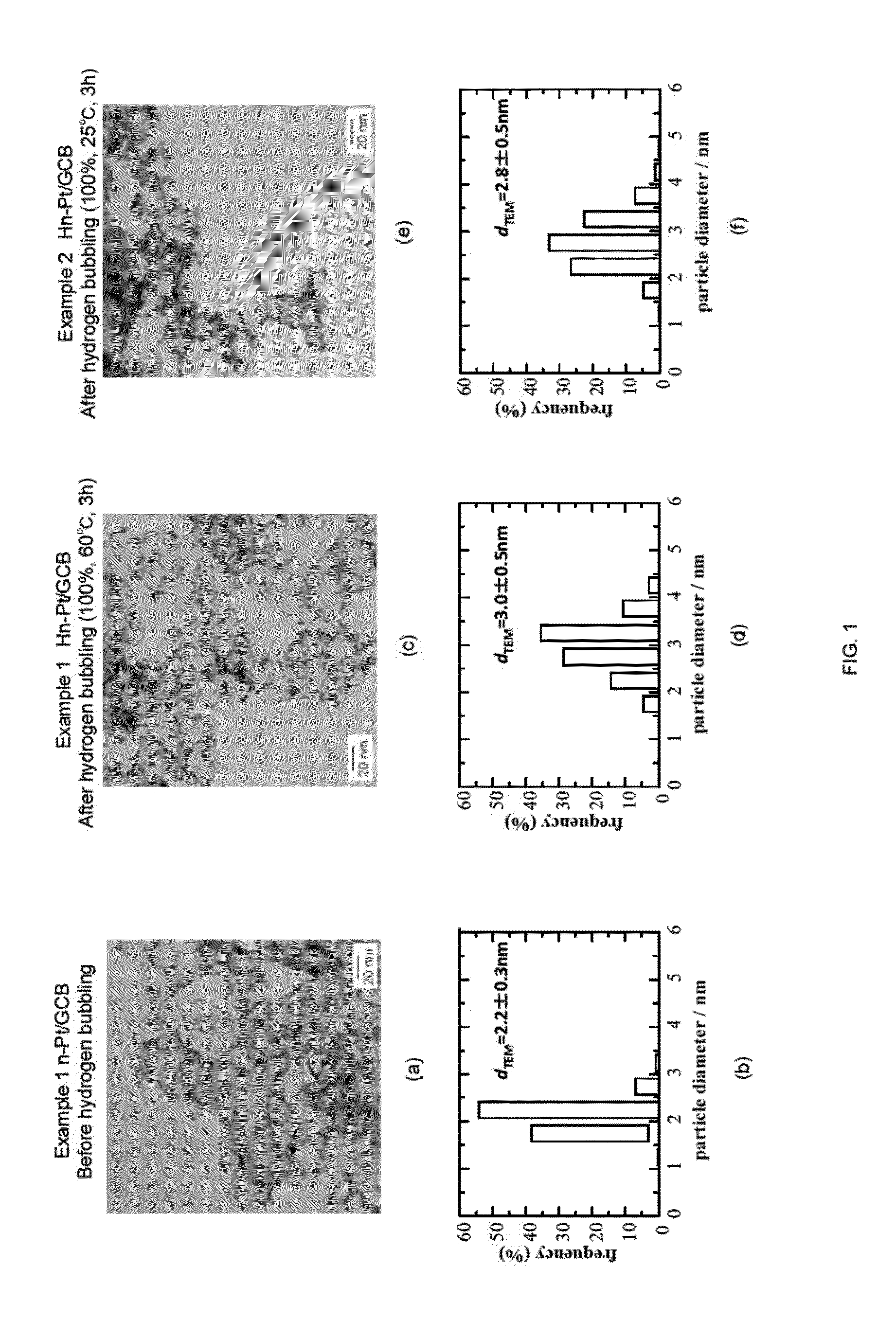
n-Pt / GCB+Pt Skin (Hn-Pt / GCB), 100% Hydrogen Bubbling, 60° C., 3 h

[0085]1-1. Preparation of n-Pt / GCB

[0086]Pt(acac)2 (0.125 mmol, 49 mg), 1,2-hexadecanediol (1 mmol, 260 mg), and diphenyl ether (12.5 ml, 13.5 g, 79.3 mmol) were charged in a beaker, and the mixture was agitated and mixed for 10 minutes at an elevated temperature of 100° C. using a stirrer. Subsequently, oleic acid (0.25 mmol, 85 μl) and oleylamine (0.25 mmol, 80 μl) were added, and the temperature was raised to 200° C. with agitation. Then, the mixture was further agitated for 20 minutes to give a nano-capsule solution. To the nano-capsule solution thus obtained, 1M LiB(C2H5)3H·THF solution (1.0 ml, 1 mmol) was added dropwise over 2 minutes, and the mixture was agitated for 5 minutes. Then, the temperature of the mixture was raised to 260° C., and the reduction reaction was carried out at this temperature under reflux for 20 minutes. Accordingly, solution A containing Pt particles in the nano-capsule was ob...

example 2

2. Example 2

n-Pt / GCB+Pt Skin (Hn-Pt / GCB), 100% Hydrogen Bubbling, 25° C., 3 h

[0093]The temperature of the reaction solution during the hydrogen bubbling was altered to 25° C., and the experiment and evaluation were performed in a similar manner as Example 1. The results are shown in FIG. 1(e) to (f). As shown in FIG. 1(e), it can be understood that the particle diameter of each of the Pt fine particles supported on GCB were made large. In addition, as shown in FIG. 1(f), the average particle diameter dTEM was increased by approximately 0.6 nm. These results show that reduction reaction of the Pt skin precursor occurred by hydrogen bubbling even at a low temperature as 25° C., thereby forming the Pt skin layer.

example 3

3. Example 3

n-Pt / GCB+Pt Skin (Hn-Pt / GCB), 5% Hydrogen Bubbling, 25° C., 1 h

[0094]In Example 3, the conditions for the hydrogen bubbling were altered to a hydrogen concentration of 5%, a temperature of 25° C., and the time period of 1 hour, and the experiment and evaluation were performed in a similar manner as Example 1. The results are shown in FIG. 2(a) to (b). As shown in FIG. 2(a), it can be understood that the particle diameter of each of the Pt fine particles supported on GCB were made large. In addition, as shown in FIG. 2(b), the average particle diameter dTEM was increased by approximately 0.9 nm. These results show that almost total amount of the Pt skin precursor were reduced and consumed for the formation of the Pt skin layer, even when the hydrogen bubbling was conducted under the conditions of low concentration, low temperature, and short time, such as hydrogen concentration of 5%, temperature of 25° C., and time period of 1 hour.


PUM

PropertyMeasurementUnit
particle diameteraaaaaaaaaa
temperatureaaaaaaaaaa

Abstract

Provided is a method for efficiently manufacturing fine metal particles applicable as a fuel cell electrode catalyst. Provided is a method of manufacturing fine metal particles, including the step of: a hydrogen bubbling step to perform bubbling to a reaction solution, wherein: the reaction solution is prepared by allowing seeds of fine metal particles in a dispersed state and a water soluble noble metal precursor to co-exist in a water-containing solvent; and the bubbling is performed with a reaction gas containing a hydrogen gas, is provided.

Description

TECHNICAL FIELD[0001]The present invention relates to a method for efficiently manufacturing fine metal particles which can be used as a fuel cell electrode catalyst, a supported fine metal particle catalyst having uniform particle diameter obtained by the method, and to a fuel cell electrode catalyst.BACKGROUND[0002]As an electrode catalyst, the ones having activated metal comprising platinum as a main component being supported on a carrier comprising a conductor such as carbon, tin oxide and the like have been used. Regarding various heterogeneous catalysts, the ones having activated metal comprising noble metal, non-noble metal, or alloys thereof as its main component being supported on a carrier comprising oxides such as alumina, titania, magnesia and the like have been used.[0003]The performance of the electrode catalyst depends on the followings:(1) particle diameter of activated metal,(2) particle composition of activated metal,(3) distribution of particle diameter (whether t...

Claims


Application Information

Patent Timeline
Patent Type & Authority Applications(United States)
IPC IPC(8): H01M4/90B22F1/054B22F9/16
CPCH01M4/9075B22F9/16B22F2301/25B22F2301/255B22F2301/00B22F2301/35B22F2301/205B22F2301/20B22F2301/15B22F9/26B22F2201/013H01M4/92B22F9/22Y02E60/50B22F1/054
Inventor WATANABE, MASAHIROUCHIDA, HIROYUKIYANO, HIROSHIUCHIDA, MAKOTO
Owner UNIVERSITY OF YAMANASHI
Learn More