Renewable energy storage and zero emission power system

a technology of renewable energy storage and power system, applied in the direction of liquid gas reaction process, energy input, chemical/physical process, etc., can solve the problem that the goal is unlikely to be met by a large margin, and achieve the effect of enhancing the thermal efficiency of the co-production process

Inactive Publication Date: 2016-03-03
ZTEK
View PDF7 Cites 12 Cited by
  • Summary
  • Abstract
  • Description
  • Claims
  • Application Information

AI Technical Summary

Benefits of technology

The patent describes an energy system that uses natural gas and a fuel processor to create energy. The system is designed to be emission-free and can use CO2 to produce energy. It also recycling steam to improve efficiency and can convert renewable electricity to a form that can be stored and used as commercial power.

Problems solved by technology

However, it is reported that the goals are unlikely to be met by a large margin unless suitable technologies are developed in the near future.

Method used


Image

  • Renewable energy storage and zero emission power system
  • Renewable energy storage and zero emission power system
  • Renewable energy storage and zero emission power system

Examples


Embodiment Construction

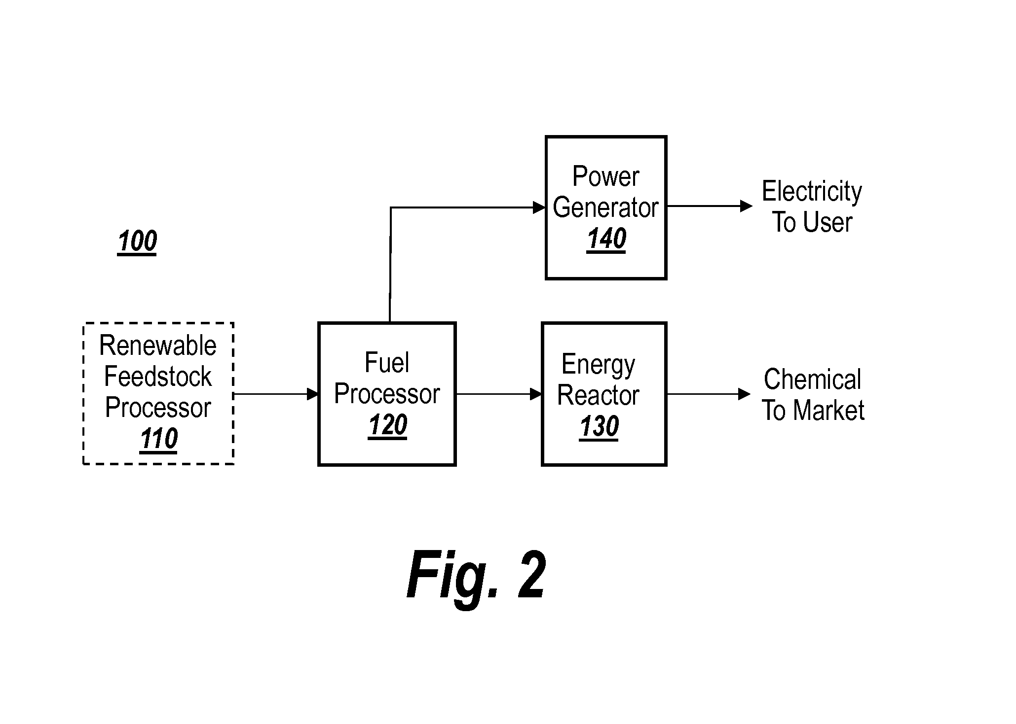
[0035]FIGS. 1 and 2 are schematic block diagrams illustrating an energy system 100 according to the teachings of the present invention. The illustrated energy system 100 can include a fuel processor 120, an energy or catalytic reactor 130, and a power generator 140. The illustrated energy system converts a carbon based fuel product into a more refined or pure fuel for subsequent use or storage.

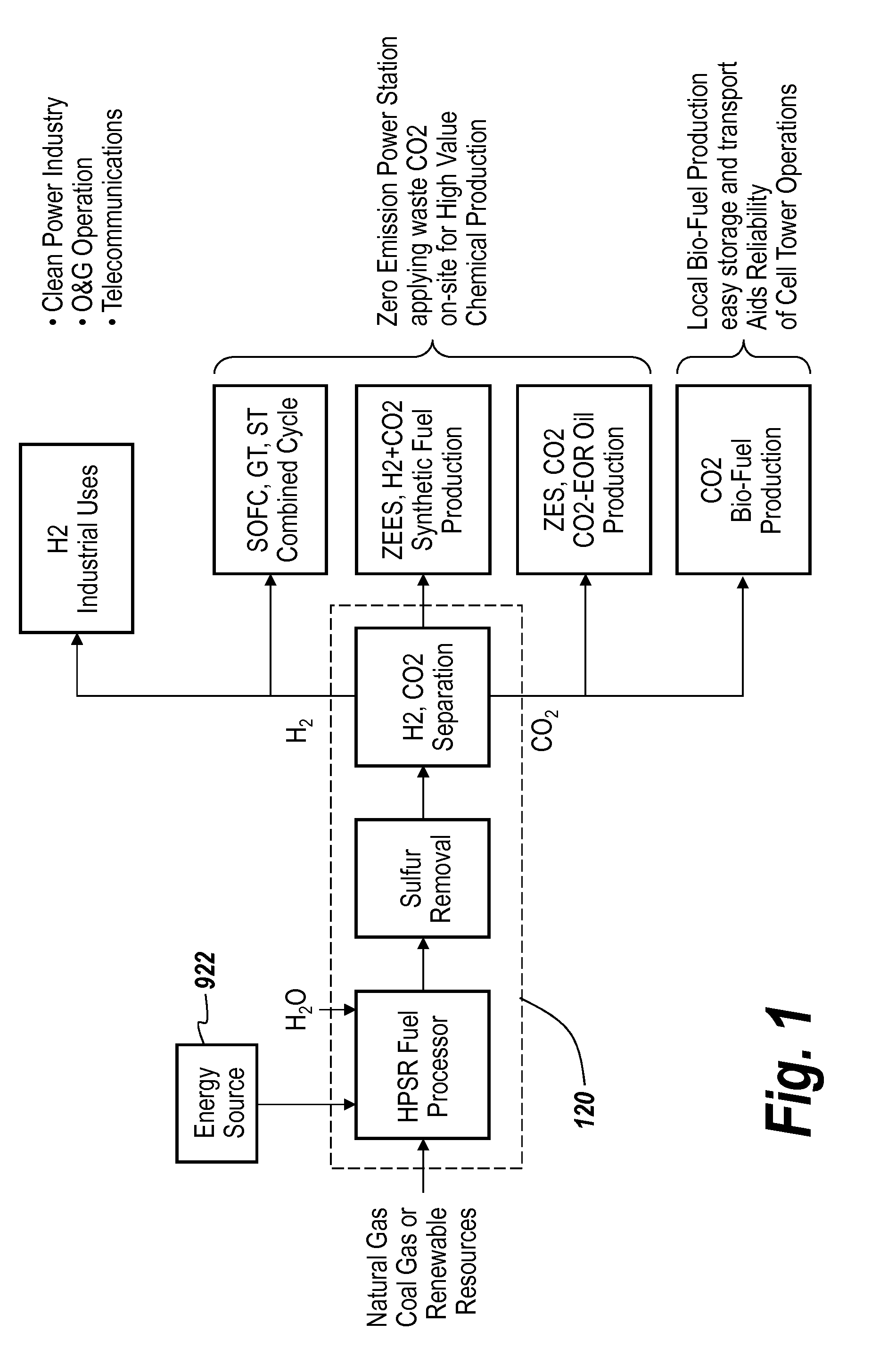
[0036]The illustrated fuel processor 120 can receive a carbon based fuel, such as natural gas, coal gas or a renewable gas, and process the gas to form a reformate, which can include H2, CO, CO2 and / or a mixture of H2,CO and CO2. The fuel processor can include any suitable type of reformer having any suitable structure or configuration, such as an autothermal reformer, a partial oxidation reformer, or a steam reformer (e.g., a steam methane reformer). As shown the reformer processes or reforms the fuel, and the processed fuel can pass through a sulfur removal apparatus for removing sulfur from...


PUM

PropertyMeasurementUnit
Shapeaaaaaaaaaa
Efficiencyaaaaaaaaaa
Energyaaaaaaaaaa

Abstract

The invention provides an energy system comprising a fuel processor for receiving a hydrocarbon fuel and for catalytically converting the hydrocarbon fuel into a reformate, an electric heating apparatus coupled to the fuel processor for providing thermal energy to the fuel processor, an energy source coupled to the electric heating apparatus for providing power thereto, and a catalytic reactor for processing the reformate and for converting the reformate into a liquid fuel.

Description

RELATED APPLICATION[0001]This application claims priority to U.S. Provisional Application No. 62 / 074,454, filed Nov. 3, 2014, and is a continuation-in-part of patent application U.S. Ser. No. 14 / 115,231, filed Jan. 24, 2014, which is a 371 application of International Application No. PCT / US2012 / 036640 filed May 4, 2012, claiming priority to U.S. Ser. No. 61 / 515,900 filed Aug. 6, 2011, U.S. Ser. No. 61 / 635,176 filed Apr. 18, 2012, and U.S. Ser. No. 61 / 482,495 filed May 4, 2011, the contents of which are hereby incorporated by reference.BACKGROUND OF THE INVENTION[0002]The present application relates to a natural gas reforming plant for producing a reformate, which includes at least H2, CO2, and CO. More particularly, the present invention relates to a reforming plant that utilizes renewable electricity for endothermic reaction heat supply, steam generation and compression power.[0003]The governmental efforts to curb greenhouse gas (GHG) emissions have been relying on the laws of indi...

Claims


Application Information

Patent Timeline
IPC IPC(8): C10G2/00C01B3/38C07C29/151C07C29/152C07C41/01C10L1/02C10L1/04C25B1/04C25B9/00
CPCC10G2/34C01B2203/062C10G2/50C07C29/1518C07C29/152C07C41/01C10L1/02C10L1/04C01B3/38C01B3/382C25B1/04C25B9/00C10L2270/023C10L2270/026C10L2290/06C10L2290/10C10L2290/42C10L2290/38C01B2203/085C01B2203/0233C01B2203/0244C01B2203/0261C01B2203/86C01B2203/148C10G2/32C01B3/384C01B2203/0283C01B2203/0405C01B2203/042C01B2203/043C01B2203/0475C01B2203/0485C01B2203/061C01B2203/066C01B2203/84C07C41/09Y02E60/36Y02P20/133Y02P20/50Y02P30/00C07C31/04C07C43/043Y02E50/10
Inventor HSU, MICHAEL, S.
Owner ZTEK
Why Eureka
Try Eureka