Hiydrodynamic and hydrosonic cavitation generator

a generator and hydrosonic technology, applied in mixers, heat production devices, heating fuel, etc., can solve the problems of inability to use rotors, bearings and mechanical seals, inability to build, low yield, etc., and achieve the effect of easy and precise adjustment, efficient processing and easy operation

Inactive Publication Date: 2016-02-25
ECHART RUBEM IOEL DOTTE
View PDF1 Cites 10 Cited by
  • Summary
  • Abstract
  • Description
  • Claims
  • Application Information

AI Technical Summary

Benefits of technology

The present invention is a method and apparatus for heating liquids and other liquids with a high efficiency using a cavitation generator. The generator can heat water or other liquids with a thermodynamic efficiency of COP greater than 2, or more than 200% regarding the power supplied to the input device. It can also perform other actions associated with the liquid cavitation phenomena, such as mineral deposit prevention, food processing, and enzyme deactivation. The generator uses hydrodynamic cavitation to generate high density microbubbles, which are accelerated and forced through a thin disk to create pressure waves. The disk vibrates at a high frequency, creating a resonating chamber where the liquid flows slowly. The resonating chamber acts as an ultrasound system, creating a cloud of microbubbles that collapse at high pressure peaks. The generator is powered by any liquid flow that sustains a heat production proportional to pressure of the working liquid. It can be powered by any type of pump or wind device, and can even be manually operated. The generator can also be used to process liquid foods, prevent enzyme deactivation, and harness the energy dissipated as vibration and noise.

Problems solved by technology

Hydrosonic cavitation devices using piezoelectric transducers are limited to small static volumes of liquids; another hydrosonic apparatus of reasonable efficiency that can process larger volumes of liquid when powered by electric motor is disclosed in U.S. Pat. No. 5,188,090 as a cylindrical rotor with several peripheral holes which rotates within a concentric housing being supported by bearings and sealed by mechanical seals; It is difficult to build, expensive and needs a pump to force liquid to pass through said housing; both the vibration produced by shock waves as the uneven erosion of the rotor caused by cavitation causes premature damages and incapacitation of rotor, bearings and mechanical seals.
The Brazilian patent application titled “cavitation and shock waves generator”, produces similar effect but at lower frequency and greater amplitude pulses and need only be driven by a pressurized liquid stream; it is mainly intended to micro-organisms mechanical destruction; Also well known are devices capable of generating hydrodynamic cavitation by forced passage of fluid through plates with small holes; they produces low yield and are susceptible to plugging and erosion by cavitation.

Method used


Image

  • Hiydrodynamic and hydrosonic cavitation generator
  • Hiydrodynamic and hydrosonic cavitation generator
  • Hiydrodynamic and hydrosonic cavitation generator

Examples


Embodiment Construction

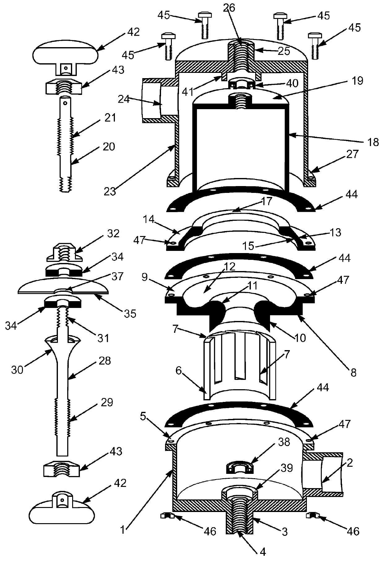
[0024]The present cavitation generator comprises:

[0025]a chamber pot-shaped, preferably cylindrical, said high pressure chamber (1) which is endowed with said feeding tube (2) suitable for connecting the chamber (1) to a pipe; said high pressure chamber (1) is endowed, on its bottom, with a support (3) with a center hole provided with internal screw thread (4) both being coincident with the axis of the chamber (1), which has, at its open end or edge, a flange (5) or other fastening means for to attach it, firmly and sealing, at the whole remainder of the apparatus body; a cylindrical tube that is positioned within said high pressure chamber (1), said vortex tube (6), provided with side openings (7) whose axes are aligned tangentially to the tube (6) circumference;

[0026]one piece said annular divider (8) with discoid shape preferably and shaped flange edges (9), suitable for tightly seal connecting to the flange (5) of said high-pressure chamber (1); said annular divider (7) being pr...


PUM


Abstract

The present invention describes a method and apparatus to use the kinetic energy available in a liquid flow to produce hydrodynamic cavitation, which, in turn, drives the hydrosonic cavitation simultaneously with sufficient efficiency and capacity to transfer the entire energy of the flow to the liquid as heat and / or another cavitation effect, thus producing physical and chemicals reactions at the molecular and atomic level.

Description

BACKGROUND OF THE INVENTION[0001]1. Field of the Invention[0002]The present invention relates generally to the formation and collapse of bubbles in hydrodynamic and hydrosonic cavitation phenomena so that the high pressures and temperatures are achieved in these bubbles collapse can be used for heating and / or to trigger and / or enhances physico-chemical transformations in liquid medium.[0003]2. Description of the Related Art[0004]The phenomenon said cavitation that occurs in liquid medium is the formations, growth and collapse of gaseous and vapor bubbles due to the reduction of surrounding pressure below the vapor pressure of the liquid at working temperature. The most widely used techniques to do that are: the generation of sound or pressure waves in the liquid using a piezoelectric transducer, said hydrosonic cavitation, and by reducing the surrounding pressure by the acceleration of a liquid flow through a Venturi tube or a orifice plate, said hydrodynamic cavitation.[0005]Hydros...

Claims


Application Information

Patent Timeline
IPC IPC(8): B01F25/25F24J3/00B01F25/451
CPCF24J3/003B01F25/25B01F25/421B01F25/4521F24V40/00
Inventor ECHART, RUBEM, IOEL, DOTTE
Owner ECHART RUBEM IOEL DOTTE
Why Eureka
Try Eureka