
Facilitated co2 transport membrane, method for producing same, resin composition for use in method for producing same, co2 separation module and method and apparatus for separating co2

Active Publication Date: 2016-02-25
RENAISSANCE ENERGY RES
View PDF22 Cites 11 Cited by
  • Summary
  • Abstract
  • Description
  • Claims
  • Application Information

AI Technical Summary

Benefits of technology

The invention provides a facilitated CO2 transport membrane and a method for its production that can stably improve the level of CO2 permeance and selective permeability. Additionally, the invention allows for the efficient separation of CO2 from a mixture of gases using the high CO2 selective permeability of the membrane.

Problems solved by technology

The step of regenerating the CO2 absorbing liquid also wastefully consumes energy because it requires a large amount of steam to remove CO2 from the CO2 absorbing liquid by heating for the reuse of the liquid.
In recent years, as a countermeasure for global warming, natural energy that does not emit CO2 has been expected to come into wide use, but natural energy has a significant problem in terms of cost.
Since the diffusion coefficient increases as the molecular diameter decreases, and the contribution of diffusivity selectivity is generally greater than that of solubility selectivity in gas separation, it is difficult to allow selective passage of gases having a larger molecular diameter by suppressing passage of gases having a smaller molecular diameter among multi-component gases having different molecular diameters.

Method used


Image

  • Facilitated co2 transport membrane, method for producing same, resin composition for use in method for producing same, co2 separation module and method and apparatus for separating co2
  • Facilitated co2 transport membrane, method for producing same, resin composition for use in method for producing same, co2 separation module and method and apparatus for separating co2
  • Facilitated co2 transport membrane, method for producing same, resin composition for use in method for producing same, co2 separation module and method and apparatus for separating co2

Examples


first embodiment

[0053]First, an embodiment of a facilitated CO2 transport membrane, an embodiment of a method for the production thereof, and an embodiment of a resin composition for use in the production method, according to the present invention (hereinafter, referred to as “the present facilitated transport membrane,”“the present production method,” and “the present resin composition,” respectively, as needed) will be described with reference to the drawings.

[0054]The present facilitated transport membrane is a facilitated CO2 transport membrane including a separation-functional membrane that includes a water-containing hydrophilic polymer gel membrane containing a CO2 carrier and a CO2 hydration catalyst having catalytic activity at a temperature of 100° C. or higher, the facilitated CO2 transport membrane having a high CO2 permeance and a high CO2 selective permeability. To stably exhibit a high CO2 selective permeability, the present facilitated transport membrane further includes a hydrophil...

synthesis example 1

Synthesis of Vinyl Acetate-Methyl Acrylate Copolymer

[0084]A 2-L-volume reaction vessel equipped with a stirrer, a thermometer, a N2 gas inlet tube, a reflux condenser, and dropping funnels was charged with 768 g of water and 12 g of anhydrous sodium sulfate, and the air in the system was replaced by N2 gas. The vessel was then charged with 1 g of partially saponified polyvinyl alcohol (88% in saponification degree) and 1 g of lauryl peroxide. After the internal temperature was raised to 60° C., 104 g (1.209 mol) of methyl acrylate and 155 g (1.802 mol) of vinyl acetate as monomers were each simultaneously added dropwise from a dropping funnel for each monomer over 4 hours. During the dropwise addition, the internal temperature was kept at 60° C. at a stirring rate of 600 rpm. After the dropwise addition was completed, the mixture was further stirred for 2 hours at an internal temperature of 65° C. The resultant mixture was then dewatered by centrifugation, so that 288 g of a vinyl a...

production example 1

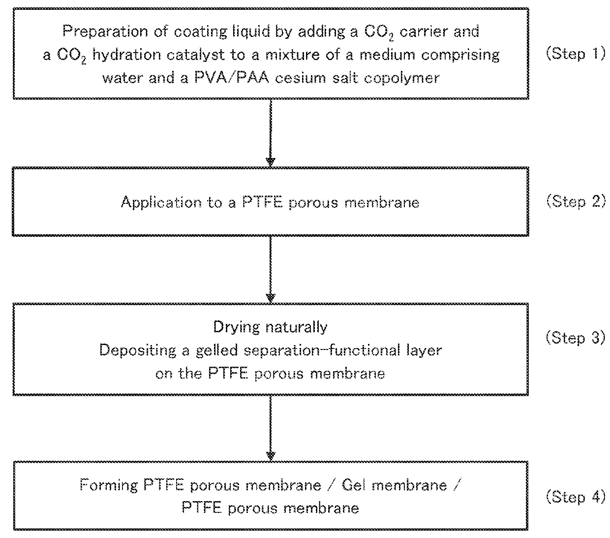
Production of PVA / PAA Cesium Salt Copolymer

[0085]A 2-L-volume reaction vessel equipped with a stirrer, a thermometer, a N2 gas inlet tube, a reflux condenser, and dropping funnels was charged with 500 g of methanol, 410 g of water, 554.2 g (3.3 mol) of cesium hydroxide monohydrate, and 288 g of the vinyl acetate-methyl acrylate copolymer (with a water content of 10.4%) obtained in Synthesis Example 1. The mixture was subjected to saponification under 400 rpm stirring at 30° C. for 3 hours. After the saponification was completed, the resultant reaction mixture was washed three times with 600 g of methanol, filtered, and dried at 70° C. for 6 hours to give 308 g of a vinyl alcohol-cesium acrylate copolymer.

Subsequently, 308 g of the vinyl alcohol-cesium acrylate copolymer was pulverized with a jet mill (LJ manufactured by Nippon Pneumatic Mfg. Co., Ltd.), so that 280 g of fine powder of the vinyl alcohol-cesium acrylate copolymer was obtained.

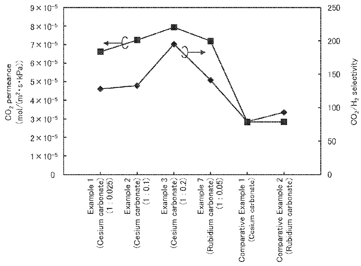
[0086]The samples in Examples 1 to 7 and C...


PUM

PropertyMeasurementUnit
Temperatureaaaaaaaaaa
Weightaaaaaaaaaa
Solubility (mass)aaaaaaaaaa

Abstract

Provided is a facilitated CO2 transport membrane having improved CO2 permeance and improved CO2 selective permeability. The facilitated CO2 transport membrane includes a separation-functional membrane comprising a hydrophilic polymer gel membrane which contains a CO2 carrier and a CO2 hydration catalyst, wherein the hydrophilic polymer is a copolymer including a first structural unit derived from an acrylic acid cesium salt or an acrylic acid rubidium salt and a second structural unit derived from vinyl alcohol. More preferably, the CO2 hydration catalyst has catalytic activity at a temperature of 100° C. or higher.

Description

CROSS-REFERENCE TO RELATED APPLICATIONS[0001]This application is a National Phase filing under 35 U.S.C. §371 of International Application No. PCT / JP2014 / 058047 filed on Mar. 24, 2014, which claims priority to Japanese Patent Application No. 2013-073644 filed on Mar. 29, 2013.TECHNICAL FIELD[0002]The present invention relates to a facilitated CO2 transport membrane for use in separating carbon dioxide (CO2), particularly to a facilitated CO2 transport membrane designed to separate carbon dioxide with high CO2 selective permeability from a mixed gas containing carbon dioxide and at least one gas selected from hydrogen, helium, nitrogen, oxygen, carbon monoxide, hydrocarbon (such as methane, ethane, or propane), and unsaturated hydrocarbon (such as ethylene or propylene) and the like. The present invention further relates to a method for producing the facilitated CO2 transport membrane and to a method and an apparatus for separating CO2 using the facilitated CO2 transport membrane.BAC...

Claims


Application Information

Patent Timeline
IPC IPC(8): B01D69/14B01D53/22B01D63/06B01D67/00B01D71/38B01D71/40B01D71/80C01B32/50
CPCB01D69/145B01D63/06B01D69/142B01D53/228B01D71/38B01D71/40B01D71/80B01D67/0079B01D61/38C08F230/00Y02C20/40B01D67/00793B01D71/381
Inventor OKADA, OSAMUHANAI, NOBUAKIYAN, PENGMIYATA, JUNYANAKASUJI, TAKEHIROSUGIYAMA, HAYATO
Owner RENAISSANCE ENERGY RES
Learn More