


Quick Research
Generate reliable direction feasibility study reports for your R&D in just a few steps.

Technical Q&A
Discover and master advanced knowledge NOW. Basics, ideas, possibilities, all at once.

Find Solutions
As an expert in R&D theories, this can generate solutions to your technical problems instantly.

Evaluate Feasibility
Analyze your overall solution with one click, know your potential R&D risks in advance.

Monitor Landscape
Get weekly tech updates, stay abreast of the latest tech innovations and key insights.
Particle beam irradiation room and particle beam therapy system
a particle beam therapy and particle beam technology, applied in the field of particle beam irradiation room of can solve the problems of affecting the effective operation and achieve the effect of enhancing the utilization efficiency of the particle beam therapy system
- Summary
- Abstract
- Description
- Claims
- Application Information
AI Technical Summary
Benefits of technology
Problems solved by technology
Method used
Image


Examples
embodiment 1
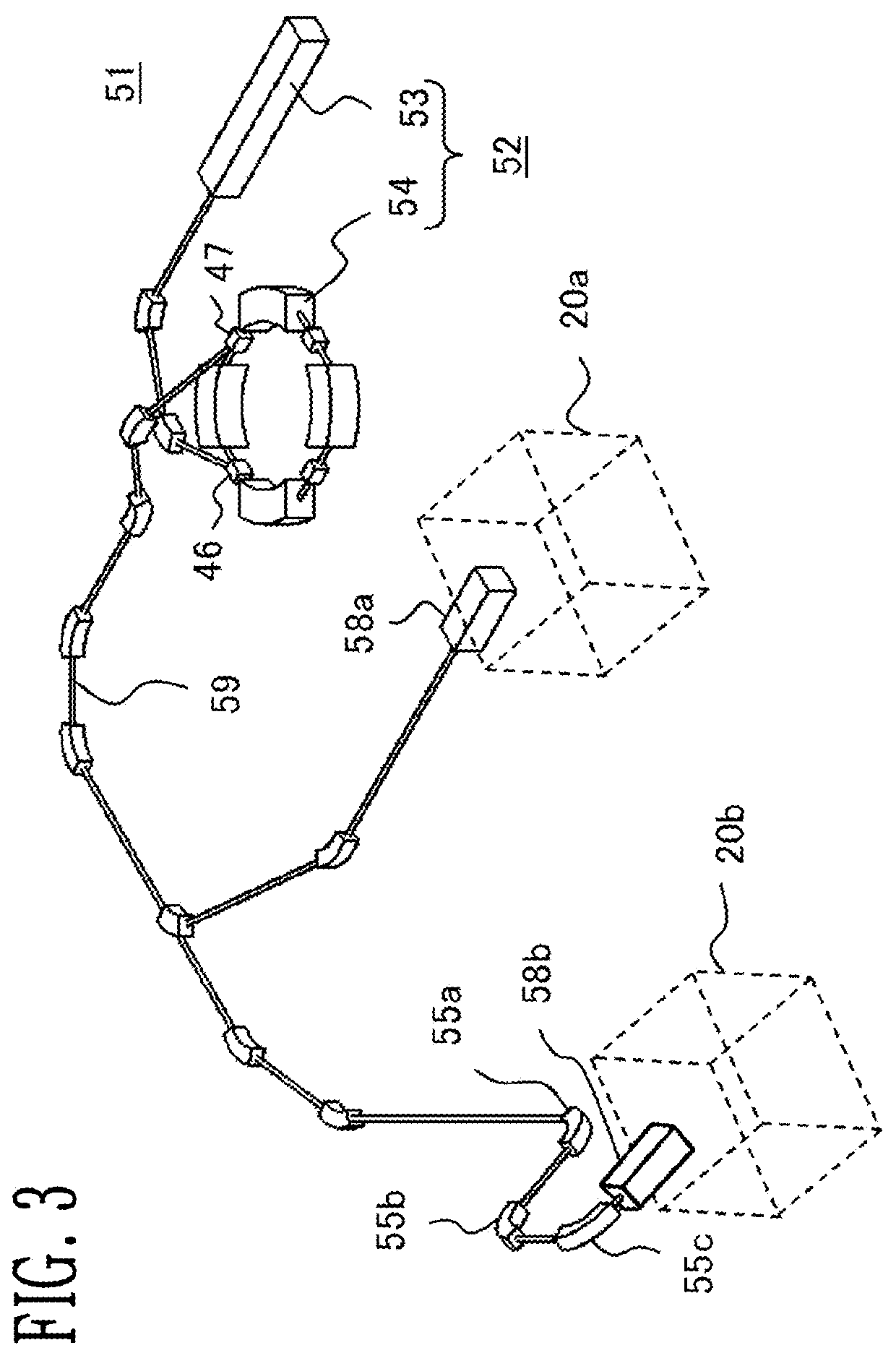
[0022]A particle beam irradiation room and particle beam irradiation apparatus provided with the particle beam irradiation room of the invention will be described. FIG. 1 is a diagram showing a particle beam irradiation room according to Embodiment 1 of the invention, and FIG. 2 is a diagram illustrating an attitude of a patient at the time of transportation of the patient according to Embodiment 1 of the invention. FIG. 3 is a schematic configuration diagram of a particle beam therapy system provided with a particle beam irradiation room of the invention, and FIG. 4 is a diagram showing a configuration of the particle beam irradiation apparatus in FIG. 3. FIG. 5 is a diagram showing a patient-position setting system of the invention. FIGS. 6A and 6B are diagrams showing a patient table in FIG. 5, and FIG. 7 is a diagram showing a transport apparatus in FIG. 5. A particle beam irradiation room 20 (referred to as an irradiation room, if appropriate) according to Embodiment 1 of the i...
embodiment 2
[0045]FIG. 9 is a diagram showing a particle beam irradiation room according to Embodiment 2 of the invention. The particle beam irradiation room 20 of Embodiment 2 differs from the particle beam irradiation room 20 of Embodiment 1 in that a shielding door 24 is provided also at the irradiation-execution-room entrance 29. In FIG. 9, numeral 24b is given to the shielding door at the time of transportation of the patient 45 laid on the top board 5, and numeral 24c is given to the shielding door at the time of radiation of the particle beam. In Embodiment 2, there is placed a plurality of shielding doors 24, so that the plurality of shielding doors are each allowed to have a lower shielding effect as compared with the case of shielding only by one of them against the leakage radiation produced during the particle beam therapy. Accordingly, restrictions in design of them can be reduced as compared with the shielding door 24 of Embodiment 1, so that it is possible to prepare these shield...
PUM
 Abstract
Description
Claims
Application Information
 - R&D Engineer
- R&D Manager
- IP Professional
- Industry Leading Data Capabilities
- Powerful AI technology
- Patent DNA Extraction
Browse by: Latest US Patents, China's latest patents, Technical Efficacy Thesaurus, Application Domain, Technology Topic, Popular Technical Reports.
© 2024 PatSnap. All rights reserved.Legal|Privacy policy|Modern Slavery Act Transparency Statement|Sitemap|About US| Contact US: help@patsnap.com