
Woven retention devices, systems and methods

a technology of retention device and woven fabric, applied in the field of woven retention device and system and method, can solve the problems of loss of purchase and holding strength of bone screw, loss of fixation or grip between bone screw and patient's bone, stripping of hole,

Active Publication Date: 2016-02-11
WOVEN ORTHOPEDIC TECH
View PDF0 Cites 19 Cited by
  • Summary
  • Abstract
  • Description
  • Claims
  • Application Information

AI Technical Summary

Benefits of technology

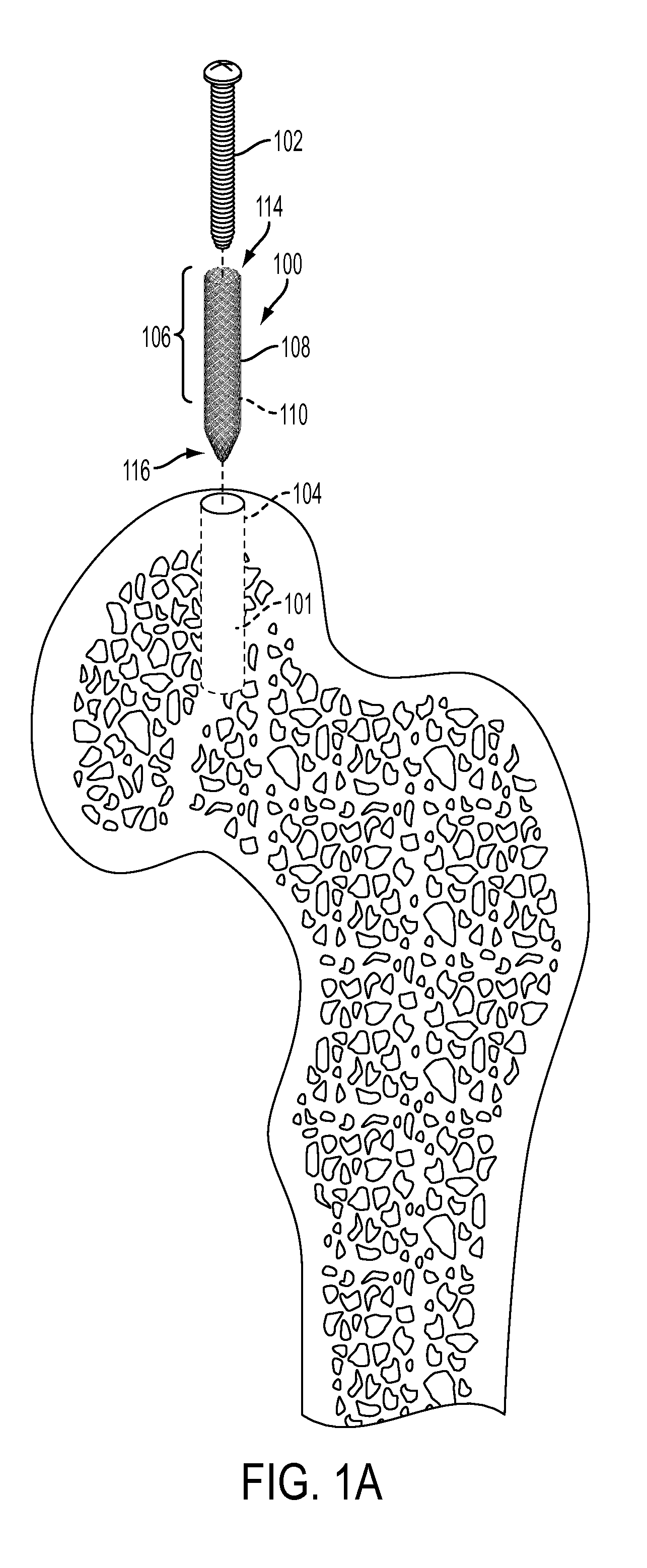
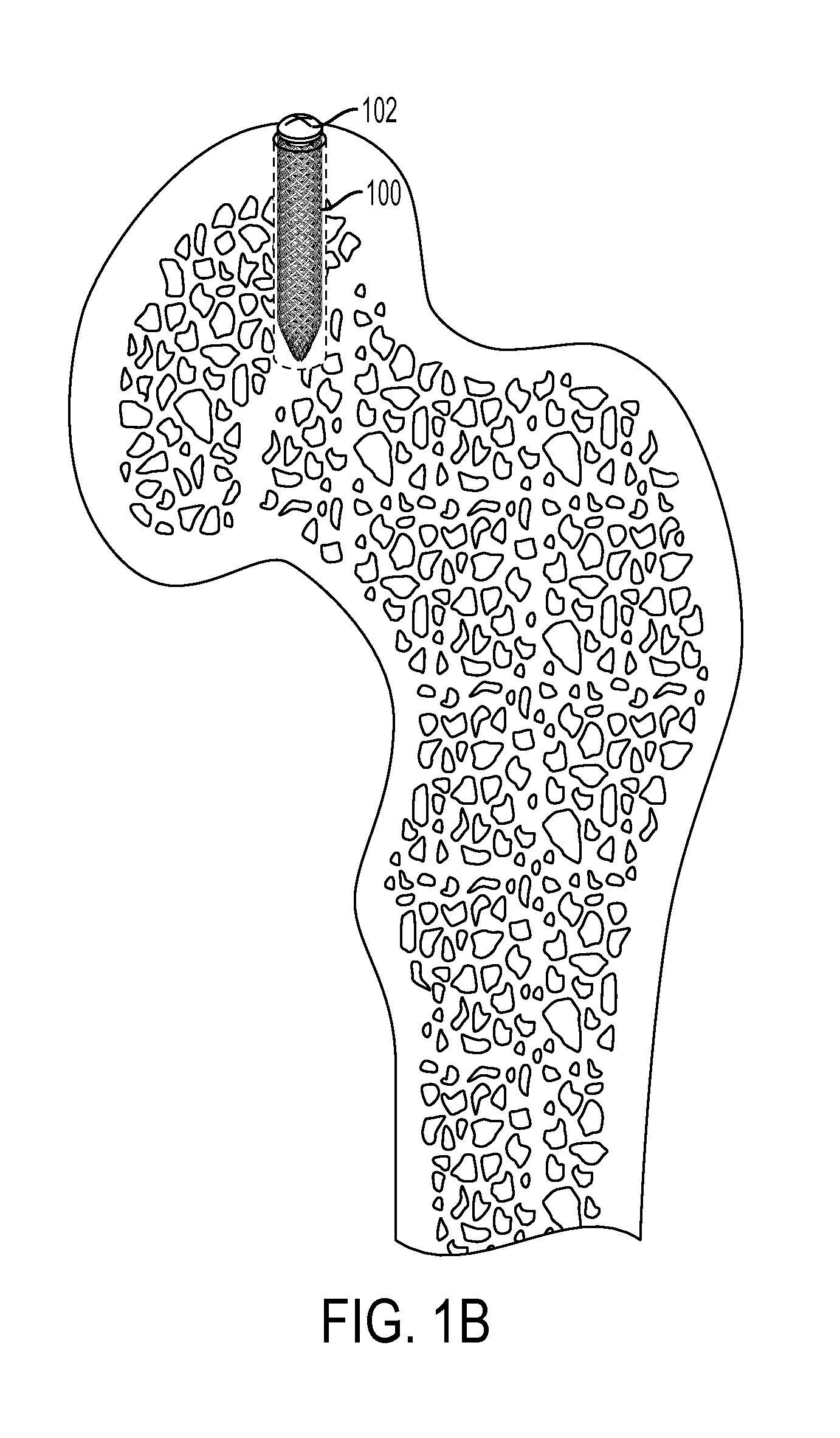
The present invention provides a retention device that can be inserted into a bone tunnel and used to secure bone fragments in place. The device has a tubular lattice made up of intersecting fibers that can be expanded and stabilized using a fastener. The device has a three-dimensional structure that allows for applied pressure to be distributed evenly to the bone surface, promoting bone growth and healing. The method of using the device involves inserting it into a bone hole and adjusting pressure from the fastener to match the bone density and shape of the fastener's interfacing surface. This invention provides a more effective and secure way to secure bone fragments during spine surgery.

Problems solved by technology

One complication with the use of bone screws is the loss of fixation or grip between the bone screw and the patient's bone.
Another complication with the use of bone screws is the stripping of the hole in the bone when the bone screw is inserted.
This results in the loss of purchase and holding strength of the bone screw.
The presence of osteoporotic bone can increase the likelihood of complications by reducing the purchase or grip of the bone screw to the patient's bone, resulting in a loss of holding strength and loosening of the bone screw or pullout of the bone screw.
Current solutions to secure bone screws have not adequately addressed screw failure and the underlying causes of screw failure.

Method used


Image

  • Woven retention devices, systems and methods
  • Woven retention devices, systems and methods
  • Woven retention devices, systems and methods

Examples


Embodiment Construction

[0073]The devices, systems and methods described herein may be used in the area of orthopedics and, in particular, orthopedic repairs. These include various devices, systems and methods directed to fixing and / or retaining fasteners in orthopedic applications. Fixing or retaining fasteners to bone tissue is complicated by the underlining bone tissue. Understanding that an underlying cause of failure with internal fixation in bone tissue is the bone, the devices, systems and methods described herein provide for solutions that address the implant site. At the implant site, the hole and the bone benefit from an enhanced interface.

[0074]The fixation and / or retention devices, systems and methods described herein maximize fixation and / or retention in the bone tissue, including, osteoporotic bone, bone of a poor quality, and mechanically poor bone in addition to healthy bone tissue. The fixation and / or retention devices, systems and methods described herein may be used with any type of fixa...


PUM


Abstract

A woven retention device for interfacing with a bone surface is provided that includes a sleeve body that can surround a fastener, a proximal end for receiving the fastener, and a distal end. The sleeve body includes interwoven monofilaments of different diameters forming a substantially tubular lattice with protuberances distributed on interior and exterior surfaces of the lattice at a predetermined spatial relationship. In a first state, the sleeve body has a plurality of combinations of filament cross-section geometries at the intersection points, forming a plurality of protuberance thicknesses as measured in a radial direction of the sleeve body. In a second state when a fastener is inserted into the tubular lattice, pressure from the fastener is transmitted to the tubular lattice such that the spatial relationship of the protuberances changes according to a function of bone density and an interfacing surface shape of the fastener.

Description

CROSS-REFERENCE TO RELATED APPLICATIONS[0001]This application claims priority to U.S. Provisional Application No. 62 / 033,455, filed Aug. 5, 2014, the disclosure of which is incorporated herein by reference in its entirety.TECHNICAL FIELD[0002]The present invention relates to devices, systems and methods for use in fixing fasteners to bone tissue.BACKGROUND[0003]In orthopedic surgery it is common to secure a bone screw to a patient's bone. Bone fracture repair is surgery to fix a broken bone using plates, nails, screws, or pins. It is common in the treatment of fractures to attach a plate to the bone utilizing bone screws. The resulting construct prevents motion of the fractured bone so that the bone can heal. Alternatively, one or more screws may be inserted across the break to hold it place.[0004]In the treatment of spinal disorders, pedicle screws are inserted into the patient's vertebrae to serve as anchor points that can then be connected with a rod. This construct prevents moti...

Claims


Application Information

Patent Timeline
Patent Type & Authority Applications(United States)
IPC IPC(8): A61B17/86
CPCA61B17/869A61B2017/8655A61B17/86A61B17/686D04C1/06D10B2509/00A61B17/8625A61B17/8685
Inventor MCDONNELL, CHRISTOPHER
Owner WOVEN ORTHOPEDIC TECH
Learn More