Sample preparation method and sample preparation device for maldi
a sample preparation and sample technology, applied in the direction of chemical vapor deposition coating, particle separator tube details, coating, etc., can solve the problems of impaired positional information of the substance to be measured on the sample, unclearness, and difficulty in enhancing the spatial resolution of mass spectroscopy imaging, so as to save preparation labor and enhance the spatial resolution , the effect of high detection sensitivity
- Summary
- Abstract
- Description
- Claims
- Application Information
AI Technical Summary
Benefits of technology
Problems solved by technology
Method used
Image

Examples
first embodiment
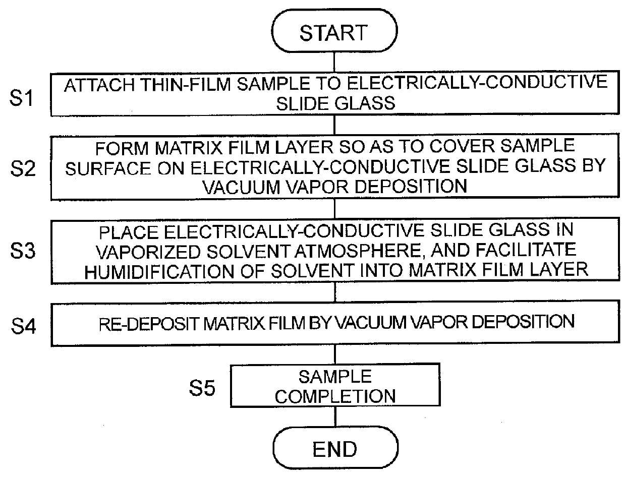
[0061]FIG. 1 is a flowchart illustrating a procedure of processing in a sample preparation method for MALDI according to a first embodiment in the present invention. FIGS. 4A to 4D are cross-sectional conceptual diagrams of a prepared sample.
[0062]First, an operator places a thin-film sample 2 such as a tissue section, which is a target to be measured, on an electrically-conductive slide glass 1 that corresponds to a sample substrate in the present invention (Step S1). It is noted that a metallic plate such as stainless steel may be employed as the sample substrate, besides the electrically-conductive slide glass.
[0063]Subsequently, a film layer of a predetermined matrix substance is formed by a vacuum vapor deposition method so as to cover the whole of the sample 2 placed on the electrically-conductive slide glass 1 (Step S2). As the matrix substance, substances generally used in a conventional sample preparation method for MALDI, for example, DHB, CHCA (α-cyano-4-hydroxycinnamic a...
second embodiment
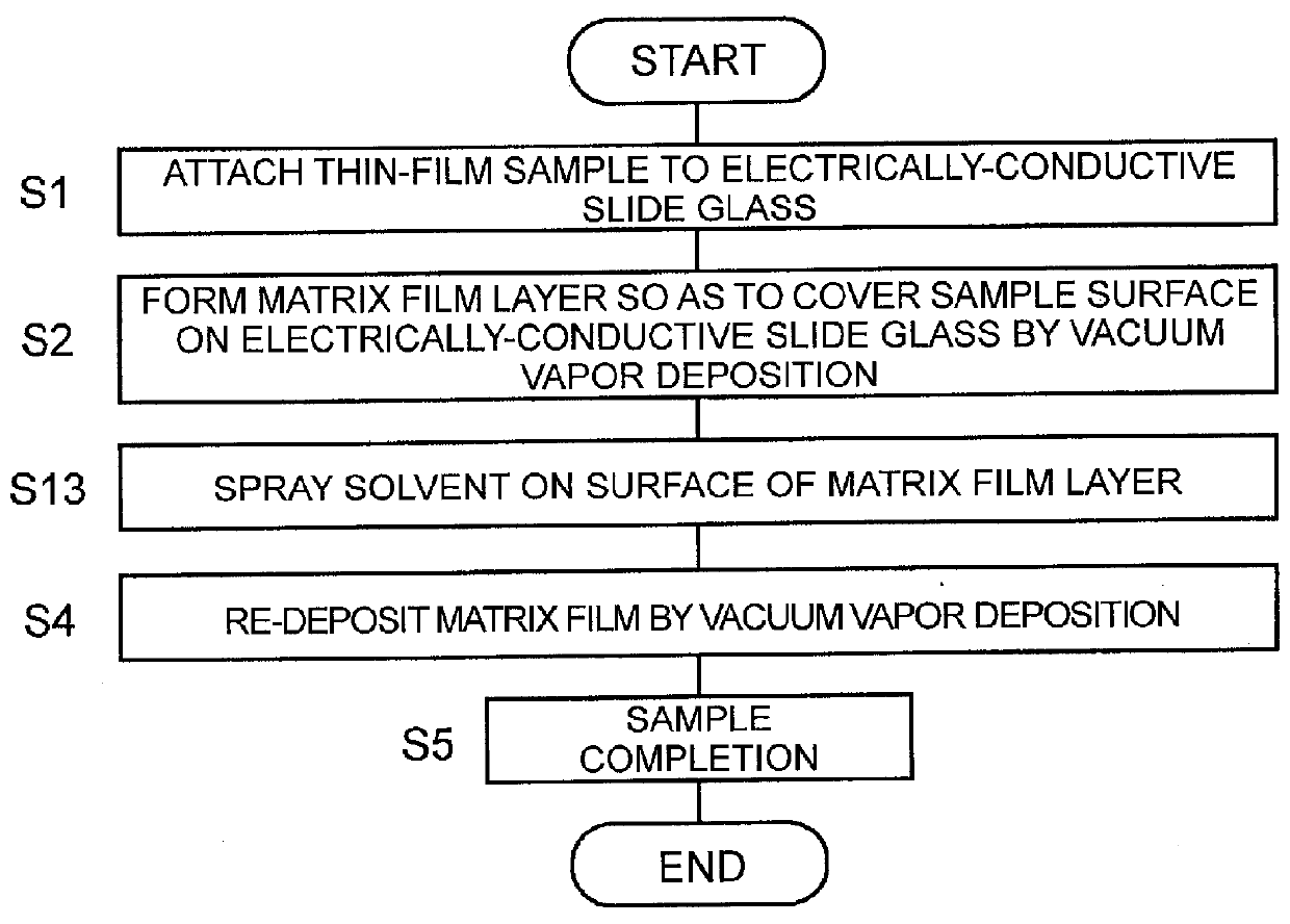
[0071]FIG. 2 is a flowchart illustrating a procedure of processing in a sample preparation method for MALDI according to a second embodiment in the present invention. Only Step S3 in the first embodiment is changed to Step S13, and each step except for Step S13 is the same with that of the first embodiment.
[0072]In the sample preparation method for MALDI in the second embodiment, the solvent is directly sprayed with a spray device such as an airbrush on the surface of the matrix film layer 3 formed on the electrically-conductive slide glass 1. This attaches the minute droplets of the solvent to the surface of the matrix film layer 3 and infiltrates the solvent into the matrix film layer 3 (Step S13).
[0073]In the sample preparation method according to the first embodiment, it takes a time, for example, the order of several hours, to cause the matrix film layer 3 to be humidified sufficiently, whereas in the sample preparation method according to the second embodiment, time required f...
third embodiment
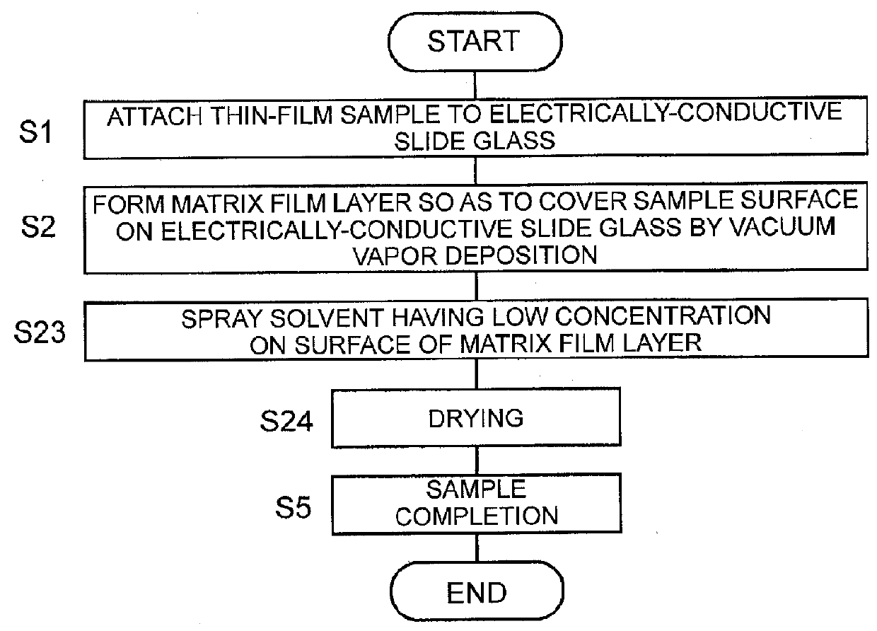
[0074]FIG. 3 is a flowchart illustrating a procedure of processing in a sample preparation method for MALDI according to a third embodiment in the present invention. Although Steps S1 and S2 are exactly identical to those in the sample preparation method in the first embodiment, the processes in Step S3 onward are different.
[0075]In the sample preparation method for MALDI according to the third embodiment, after the matrix film layer 3 is formed on the electrically-conductive slide glass 1, the matrix solution having low concentration is directly sprayed with the spray device such as the airbrush on the surface of the matrix film layer 3 (Step S23), and subsequently the matrix film layer 3 is dried to remove the solvent (Step S24). This “low concentration” means the concentration lower than the concentration of the matrix solution used in a conventional general matrix application method, and specifically, the adequate concentration is about half to one fifth of the concentration of ...
PUM
| Property | Measurement | Unit |
|---|---|---|
| Time | aaaaa | aaaaa |
| Electrical conductor | aaaaa | aaaaa |
Abstract
Description
Claims
Application Information
 - R&D
- Intellectual Property
- Life Sciences
- Materials
- Tech Scout
- Unparalleled Data Quality
- Higher Quality Content
- 60% Fewer Hallucinations
Browse by: Latest US Patents, China's latest patents, Technical Efficacy Thesaurus, Application Domain, Technology Topic, Popular Technical Reports.
© 2025 PatSnap. All rights reserved.Legal|Privacy policy|Modern Slavery Act Transparency Statement|Sitemap|About US| Contact US: help@patsnap.com