Carbon oxide reduction with intermetallic and carbide catalysts
- Summary
- Abstract
- Description
- Claims
- Application Information
AI Technical Summary
Benefits of technology
Problems solved by technology
Method used
Image

Examples
example 1
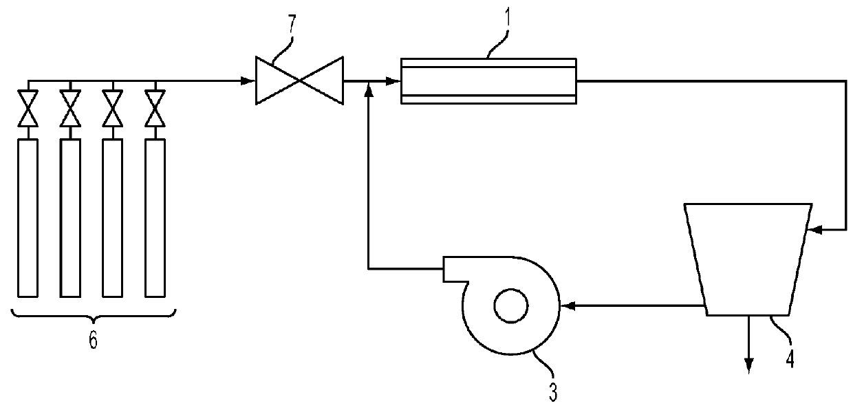
[0112]A sample of mild steel wafer with extensive red rust spots was used as the catalyst. The mild steel wafer was placed in the tube furnace 1 at approximately the centerline. The experimental apparatus was purged with helium and brought to the desired reaction temperature.
[0113]When the furnace 1 temperature reached a temperature of 680° C., the experimental apparatus was purged with reaction gases in a stoichiometric mixture of carbon dioxide and hydrogen (delivered from the gas supply 6 by the mixing valve 7) for five minutes. The reaction gases flowed through the tube furnace 1 for one hour, after which the heating element of the furnace 1 was shut off, and the experimental apparatus was purged with helium for five minutes. The furnace 1 was then left to cool.
[0114]The steel sample was removed after the furnace 1 had cooled. FIG. 3 of International Patent Publication WO 2013 / 158156 shows a photograph of the steel sample after it was removed, including a “forest” type of growth...
example 2
[0115]A quartz disk was placed lying flat on a wafer of 304 stainless steel, which was used as the catalyst. The wafer was placed in furnace 1 at approximately the centerline. The experimental apparatus was helium-purged and heated as in Example 1. Reaction gases were added and recirculated for one hour at a temperature of 680° C. and a pressure between 85.3 kPa (640 Torr) and 101.3 kPa (760 Torr), as in Example 1.
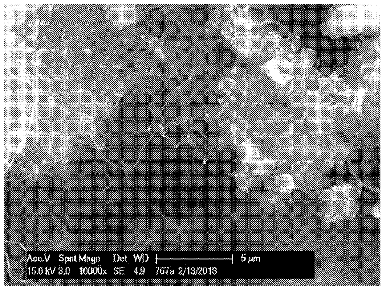
[0116]The stainless steel sample was removed from the furnace 1 after the furnace 1 had cooled. A mat of CNTs had grown between the quartz and the stainless steel wafer. Portions of the CNT mat adhered to both the quartz and the stainless steel surfaces. FIG. 7 of International Patent Publication WO 2013 / 158156 shows the sample under 10,000× magnification, and FIG. 8 of WO 2013 / 158156 shows the sample under 100,000× magnification. The size of the CNTs (tens to hundreds of nanometers in diameter) indicates that they are probably multi-wall CNTs.
example 3
[0117]A wafer of 316L stainless steel was used as the catalyst. The 316L stainless steel wafer was placed in furnace 1 at approximately the centerline. The experimental apparatus was helium-purged and heated as in Example 1. Reaction gases were added and recirculated for one hour as in Example 1, but at a temperature of 700° C. and a pressure between 93.3 kPa (700 Torr) and 97.3 kPa (730 Torr).
[0118]The stainless steel wafer was removed from the furnace 1 after the furnace 1 had cooled. FIG. 9 of International Patent Publication WO 2013 / 158156 is a photograph of the stainless steel wafer. The carbon nanotubes grew on only a portion of the wafer. The reasons for this are unclear. FIG. 10 of WO 2013 / 158156 shows an image of a region of the CNT forest on the wafer at 2,500× magnification, and FIG. 11 of WO 2013 / 158156 shows an image of the same region of the CNT forest at 10,000× magnification. The diameter of the tubes indicates that they are likely multi-wall CNTs.
PUM
| Property | Measurement | Unit |
|---|---|---|
| Temperature | aaaaa | aaaaa |
| Temperature | aaaaa | aaaaa |
| Particle size | aaaaa | aaaaa |
Abstract
Description
Claims
Application Information
 - R&D
- Intellectual Property
- Life Sciences
- Materials
- Tech Scout
- Unparalleled Data Quality
- Higher Quality Content
- 60% Fewer Hallucinations
Browse by: Latest US Patents, China's latest patents, Technical Efficacy Thesaurus, Application Domain, Technology Topic, Popular Technical Reports.
© 2025 PatSnap. All rights reserved.Legal|Privacy policy|Modern Slavery Act Transparency Statement|Sitemap|About US| Contact US: help@patsnap.com