Electrochemical reduction device and method for manufacturing hydride of aromatic compound

a technology of aromatic hydrocarbon compound and electrochemical hydrogenation, which is applied in the direction of manufacturing tools, electrode coatings, electric circuits, etc., can solve the problems of small to medium-scale manufacturing of cyclic organic compounds, difficult to industrially hydrogenate aromatic hydrocarbon compounds, and small amount of substances that can be transformed per electrode area or time (current density) that are not large, and achieve high efficiency

Active Publication Date: 2016-01-14
ENEOS CORP
View PDF6 Cites 4 Cited by
  • Summary
  • Abstract
  • Description
  • Claims
  • Application Information

AI Technical Summary

Benefits of technology

The present invention aims to provide a technique that can efficiently hydrogenate the benzene ring of an aromatic hydrocarbon compound or a nitrogen-containing heterocyclic aromatic compound using electrochemistry.

Problems solved by technology

This reaction requires reaction conditions of high temperature and high pressure, and thus is unsuitable for small to medium scale manufacturing a cyclic organic compound.
However, the amount of substance that can be transformed per electrode area or time (current density) is not large, and it has been difficult to industrially hydrogenate a benzene ring of an aromatic hydrocarbon compound.

Method used


Image

  • Electrochemical reduction device and method for manufacturing hydride of aromatic compound
  • Electrochemical reduction device and method for manufacturing hydride of aromatic compound
  • Electrochemical reduction device and method for manufacturing hydride of aromatic compound

Examples


embodiment 1

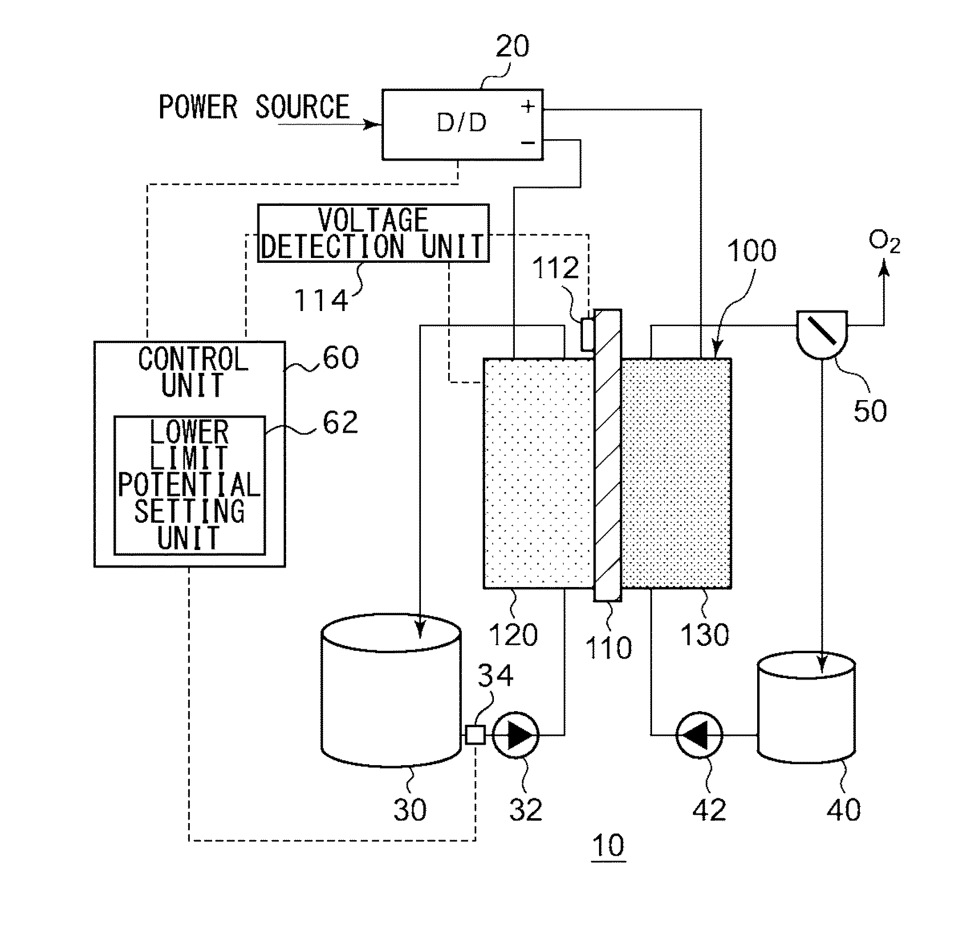
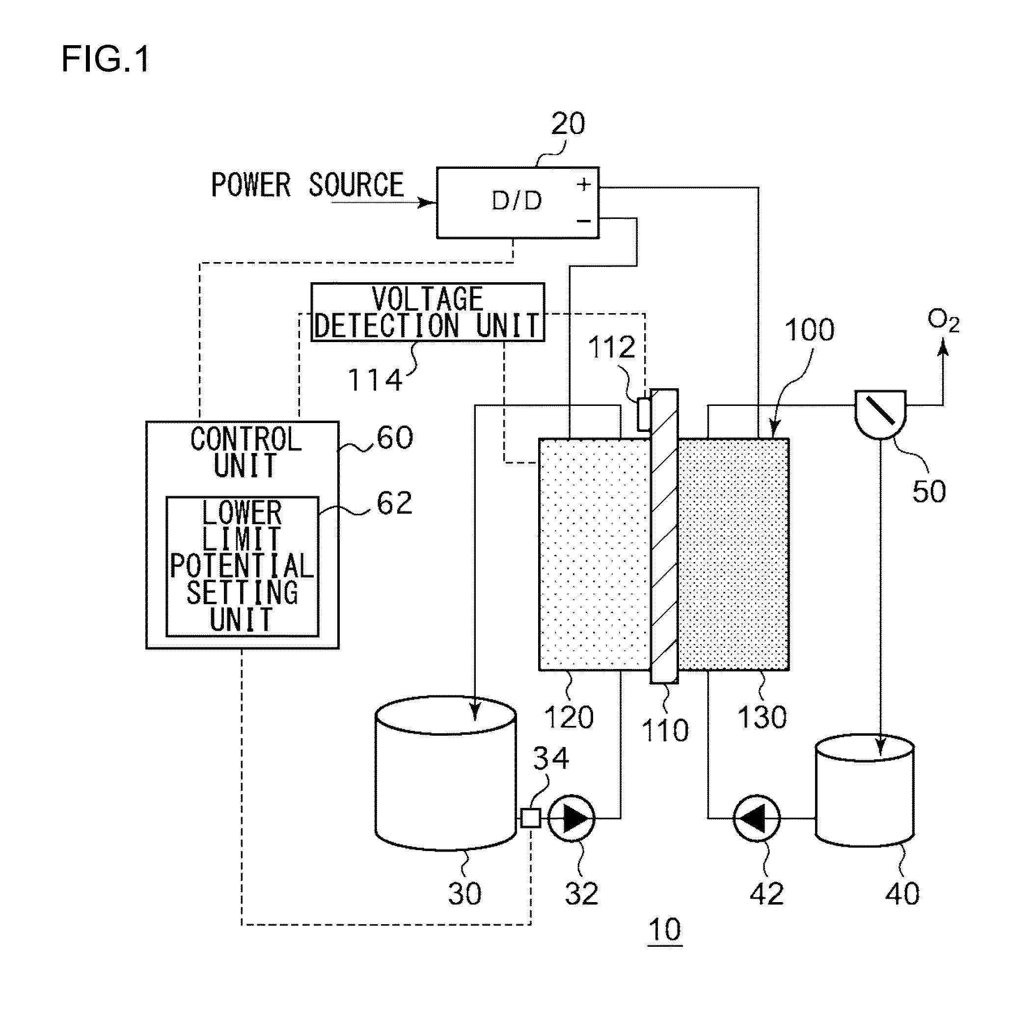
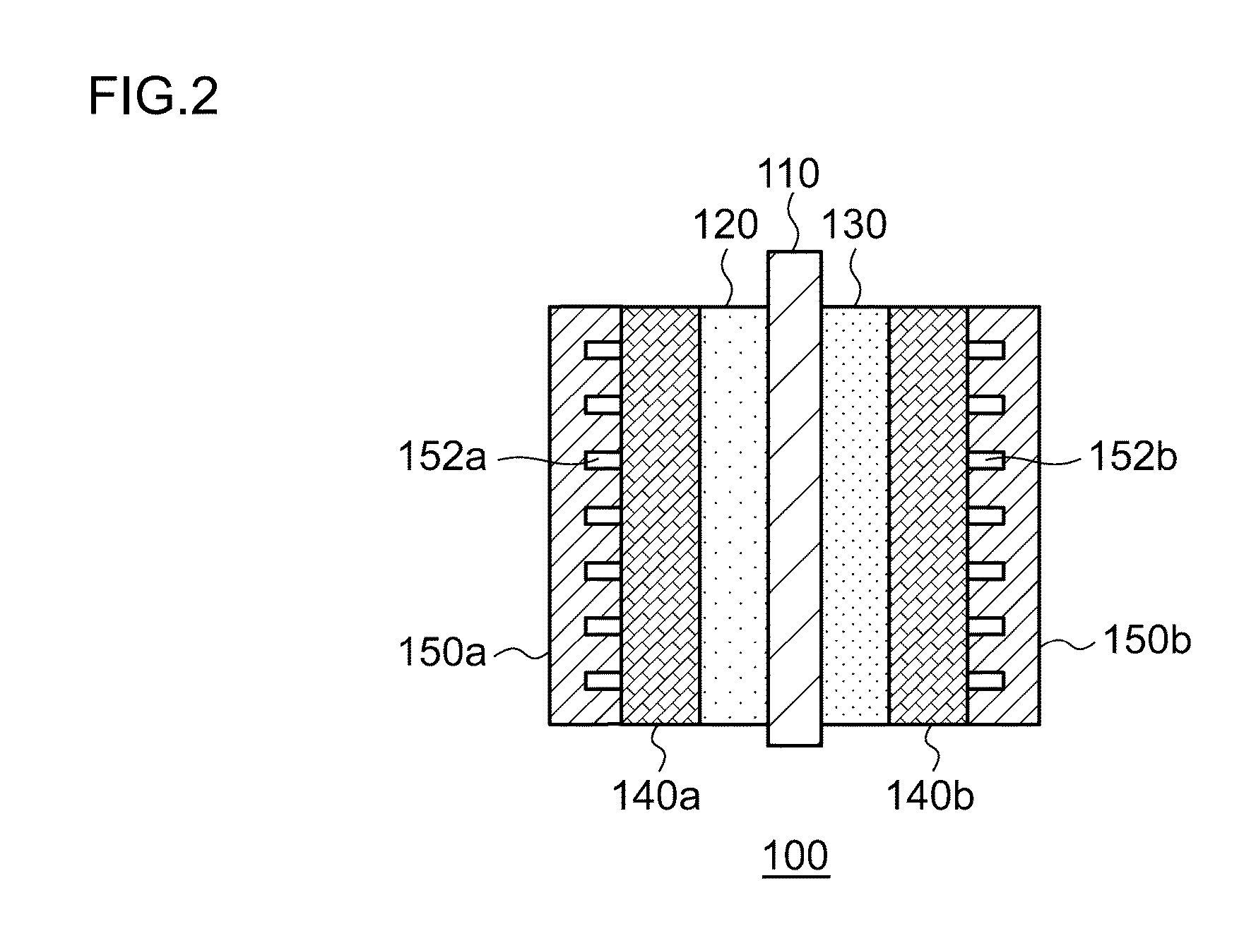
[0024]FIG. 1 is a schematic diagram illustrating the general configuration of an electrochemical reduction device 10 according to an embodiment. FIG. 2 is a diagram illustrating the general configuration of an electrode unit of the electrochemical reduction device 10 according to the embodiment. As illustrated in FIG. 1, the electrochemical reduction device 10 includes an electrode unit 100, a power control unit 20, an organic material storage tank 30, a concentration measurement unit 34, a water storage tank 40, a gas-water separation unit 50, and a control unit 60, as a main configuration. As illustrated in FIG. 2, the electrode unit 100 includes an electrolyte membrane 110, a reduction electrode 120, an oxygen evolving electrode 130, liquid diffusion layers 140a and 140b, and separators 150a and 150b. Hereinafter, the combination of the electrolyte membrane 110, the reduction electrode 120, the oxygen evolving electrode 130, the liquid diffusion layers 140a and 140b, and the sepa...

embodiment 2

[0073]FIG. 4 is a schematic diagram illustrating the general configuration of an electrochemical reduction device according to an embodiment 2. As illustrated in FIG. 4, the electrochemical reduction device 10 includes electrode units 100A, 100B, and 100C, which are each independent. In the present embodiment, the number N of the electrode units 100 is three, but the number N may be any number as long as it is equal to or more than two. The configuration of each electrode unit 100 is similar to the configuration in the embodiment 1, and the explanation about them will not be appropriately provided. In FIG. 4, the electrode unit 100 is simplified for illustration, and the liquid diffusion layers 140a and 140b and the separators 150a and 150b illustrated in FIG. 2 are not illustrated.

[0074]In the present embodiment, the power control unit 20 supplies a voltage Va (A), a voltage Va (B), and a voltage Va (C) each independently between the oxygen evolving electrode 130 and the reduction ...


PUM

PropertyMeasurementUnit
Temperatureaaaaaaaaaa
Concentrationaaaaaaaaaa
Equilibriumaaaaaaaaaa

Abstract

An electrochemical reduction device includes an electrode unit, a power control unit, an organic material storage tank, a concentration measurement unit, a water storage tank, a gas-water separation unit, and a control unit. The electrode unit includes an electrolyte membrane, a reduction electrode, and an oxygen evolving electrode. The control unit controls the power control unit so as to satisfy a relation of VHER−Vallow≦VCA≦VTRR when the potential at a reversible hydrogen electrode, the standard redox potential of the aromatic compound, and the potential of the reduction electrode are expressed as VHER, VTRR, and VCA, respectively. Vallow is adjusted according to the concentration of the aromatic compound measured by the concentration measurement unit.

Description

BACKGROUND OF THE INVENTION[0001]1. Field of the Invention[0002]The present invention relates to a technique for electrochemically hydrogenating an aromatic hydrocarbon compound or a nitrogen-containing heterocyclic aromatic compound.[0003]2. Description of the Related Art[0004]It is known that a cyclic organic compound such as cyclohexane or decalin is efficiently obtained by hydrogenating a benzene ring of a corresponding aromatic hydrocarbon compound (benzene or naphthalene) using a hydrogen gas. This reaction requires reaction conditions of high temperature and high pressure, and thus is unsuitable for small to medium scale manufacturing a cyclic organic compound. On the other hand, in an electrochemical reaction using an electrolysis cell, it is not necessary to treat gaseous hydrogen since water can be used as a source of hydrogen, and also the reaction is known to proceed under relatively mild reaction conditions (at from room temperature to about 200° C. and under normal pre...

Claims


Application Information

Patent Timeline
IPC IPC(8): C25B3/25C25B9/17C25B9/19
CPCC25B3/04C25B9/08C25B9/18C25B15/02C25B11/0478C25B13/04C25B11/0415Y02E60/36C25B3/25C25B1/04C25B9/73C25B9/19C25B9/70C25B11/057C25B11/091
Inventor SATO, YASUSHIMIYOSHI, KOTANAKAGAWA, KOJIROKOBORI, YOSHIHIRO
Owner ENEOS CORP
Why Eureka
Try Eureka