Threaded joint for steel pipes

Active Publication Date: 2015-12-24
JFE STEEL CORP
View PDF2 Cites 0 Cited by
  • Summary
  • Abstract
  • Description
  • Claims
  • Application Information

AI Technical Summary

Benefits of technology

The invention is about a special joint that can be used to connect steel pipes. It has a simple design and is very effective even when there is pressure outside the pipes. This makes it easier to create strong and secure connections between pipes.

Problems solved by technology

However, because crude oil wells and natural gas wells have recently increased in depth, and horizontal wells and directional wells have increased more than vertical wells, excavation and production environments are becoming severe.
However, the threaded joint described in Japanese Patent No. 4535064 has a problem in that the shape of the pin becomes complex and the productivity decreases, because it is necessary to form the pin nose to be discontinuous with the seal portion.

Method used


Image

  • Threaded joint for steel pipes
  • Threaded joint for steel pipes
  • Threaded joint for steel pipes

Examples


example

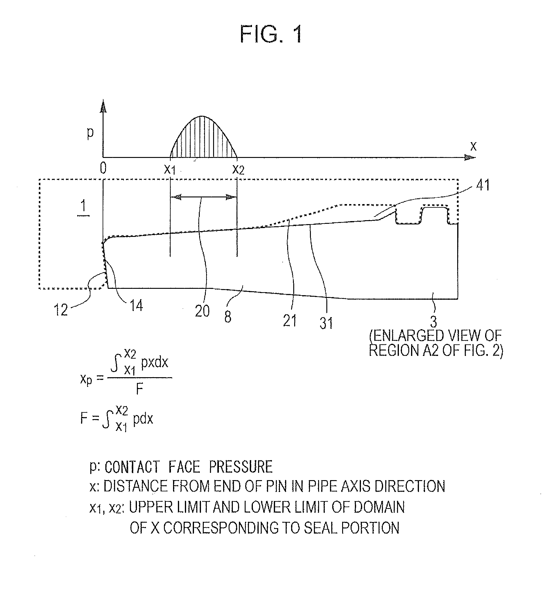
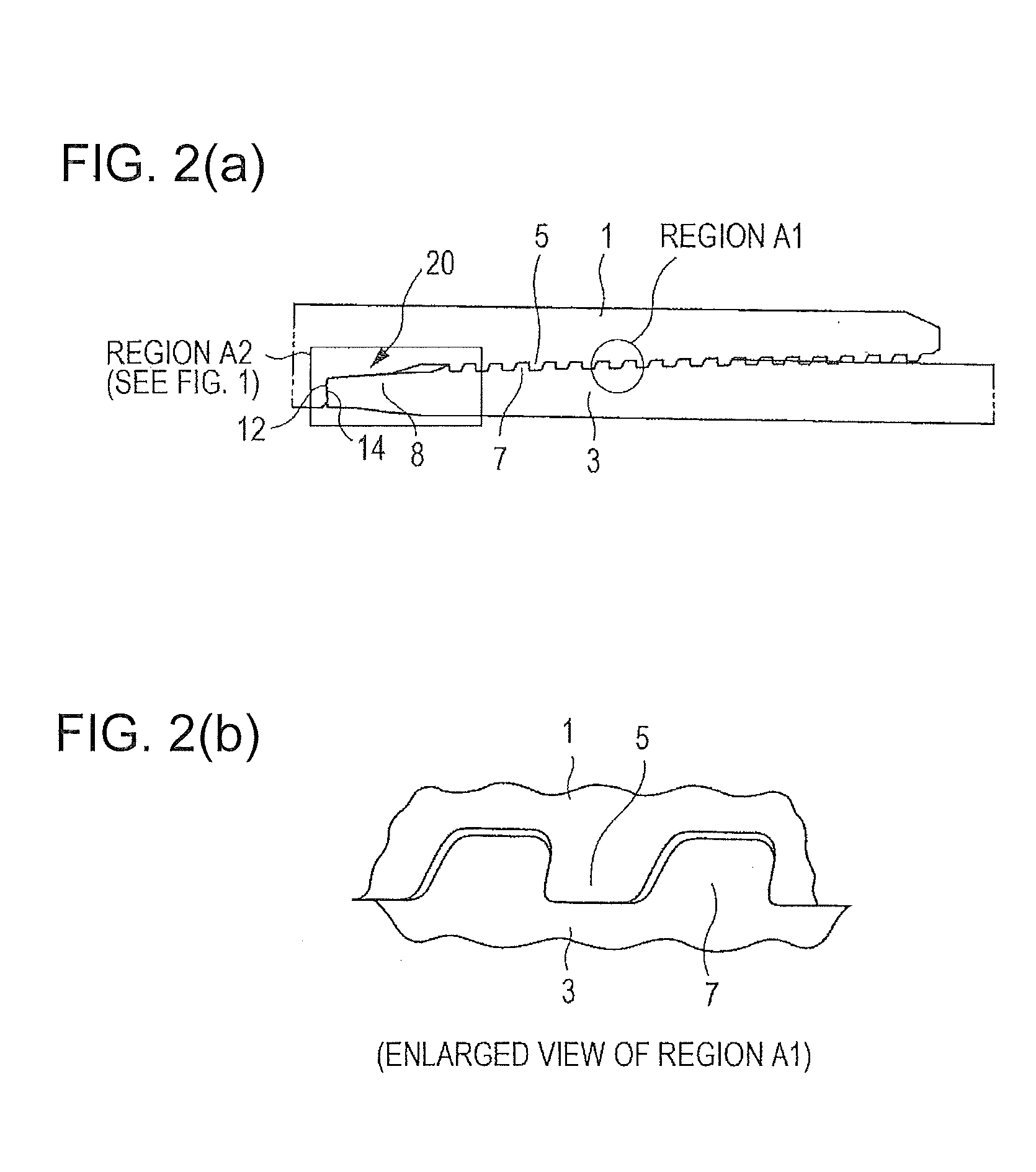
[0036]Samples of threaded joints including pins having an outside diameter of 9+⅝ inches (24.45 cm) and a thickness of 0.545 inches (1.38 cm) made by machining ends of steel pipes, and boxes corresponding to the pins were prepared so that the pins have different tapered shapes and / or the boxes have seal faces have different outwardly curved shapes. For each of these samples, the contact face pressure p was obtained by performing an FEA calculation simulating LP2 of the series A test of ISO 13679, and the seal point xp was calculated from the contact face pressure p by using equation (1). Moreover, the series A test was performed on each of the samples. Table 1 shows the results.

[0037]As shown in Table 1, it is clear that the sealability of our examples is better than that of the comparative example.

TABLE 1Seal Point xp(inches)Result of A TestExample 10.23No LeakExample 20.31No LeakExample 30.46No LeakExample 40.62No LeakComparative0.15Leak occurred in LP12.Example


PUM


Abstract

A threaded joint in which the outer peripheral face of the pin nose has a single tapered shape, the seal face of the box has an outwardly convex curved shape, and a seal point xp defined by equation (1) is greater than or equal to 0.2 inches,xp=∫x1x2pxxFF=∫x1x2px(1)where p is a contact face pressure, x is a distance from an end of the pin in a pipe axis direction, and x1 and x2 are respectively a lower limit and an upper limit of a domain of x corresponding to the seal portion.

Description

TECHNICAL FIELD[0001]This disclosure relates to a threaded joint for steel pipes and, in particular, to a threaded joint for steel pipes having high sealability and compression resistance suitable for use in connecting oil well pipes including tubing and casing generally used in prospecting for oil wells and gas wells and in production, that is, steel pipes such as oil country tubular goods (OCTG), riser pipes, and line pipes.BACKGROUND[0002]Threaded joints are widely used in connecting steel pipes such as oil well pipes, which are used in oil production facilities. To connect steel pipes for use in oil or gas prospecting and production, typical standard threaded joints based on the American Petroleum Institute (API) standard have been conventionally used. However, because crude oil wells and natural gas wells have recently increased in depth, and horizontal wells and directional wells have increased more than vertical wells, excavation and production environments are becoming sever...

Claims


Application Information

Patent Timeline
IPC IPC(8): E21B17/042F16L15/00
CPCE21B17/042F16L2201/40F16L15/00F16L15/004
Inventor NAGAHAMA, TAKUYASONOBE, OSAMUYOSHIKAWA, MASAKITAKANO, JUNKAWAI, TAKAMASA
Owner JFE STEEL CORP
Why Eureka
Try Eureka