Rolling bearing

Inactive Publication Date: 2015-06-18
NTN CORP
View PDF8 Cites 7 Cited by
  • Summary
  • Abstract
  • Description
  • Claims
  • Application Information

AI Technical Summary

Benefits of technology

The present invention relates to a sealing arrangement for bearings, which uses a harder material for one of the bearing races and a softer material for the lip. This results in a seal ring that is less likely to deform under external force, making it easier to fix the filter to the seal ring and replace the lip with a new one. This arrangement also improves sealability and prolongs the life of the seal member and of the entire bearing.

Problems solved by technology

Thus, the elastic seal member could be deformed or moved out of the correct position, thus losing its expected sealing ability, under an external force that may act on the elastic seal member during assembling or transportation of the bearing, or when the assembled bearing is mounted in a machine.
In this regard, since the elastic seal member is directly mounted on the bearing, in order to improve the accuracy of interference, it is necessary improve the dimensional accuracies of both of the elastic seal member and the bearing, which leads to increased manufacturing costs of the seal member and the bearing.
Also, since the elastic seal member is formed by molding, it is difficult to improve its dimensional accuracy beyond a certain point.

Method used


Image

  • Rolling bearing
  • Rolling bearing
  • Rolling bearing

Examples


third embodiment

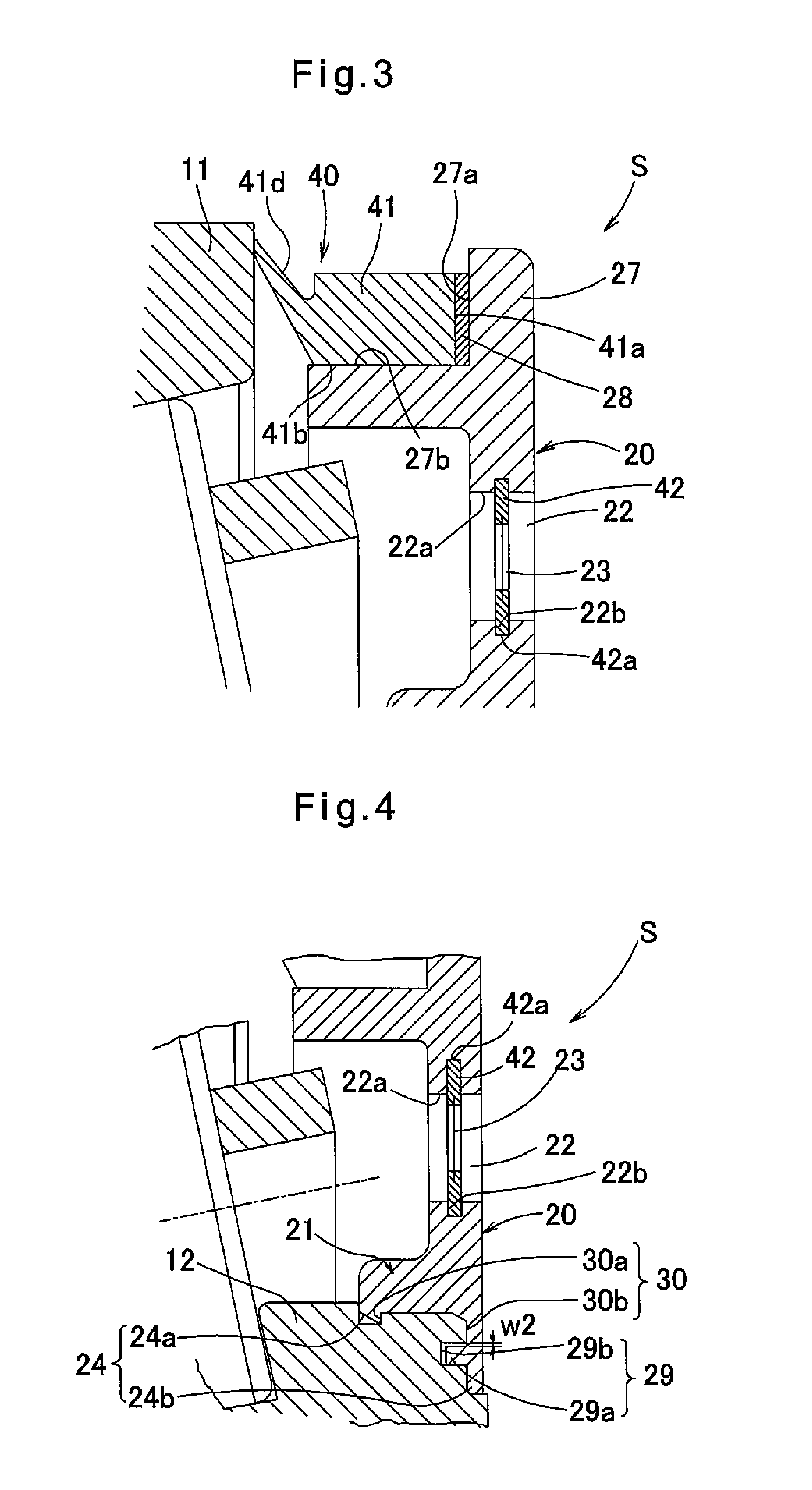
[0162]FIG. 5 shows the present invention, in which the annular member 40, forming the lip 41, is formed with a positioning shoulder 41c on its radially inner surface. The positioning shoulder 41c is configured to engage an end edge 27c (or a shoulder) of the lip mounting portion 27 of the seal ring 20, thereby axially positioning the annular member 40 relative to the seal ring 20.

[0163]In this and other embodiments, a seal ring fitting portion 31 of the engaging portion 21, defined between the inner protrusions 24a and the outer protrusions 24b, is fitted on an inner race fitting portion 32 between the inner seal grooves 30a and the outer seal grooves 30b with an interference fit. The seal ring fitting portion 31 and the inner race fitting portion 32 are fitted together with a predetermined interference fit by heating and expanding the resin seal ring 20 and fitting the thus expanded seal ring 20 onto the inner race 12. The interference fit improves sealability of the seal ring 20.

fourth embodiment

[0164]FIG. 6 shows the present invention, in which the lip mounting portion 27 of the seal ring 20 has a sectional shape of the Japanese character “”.

[0165]Since the lip mounting portion 27 has a “”-shaped section, the lip mounting portion 27 protects the annular member 40 against external force applied to the seal ring 20 from around the seal ring 20. Since the lip mounting portion 27 has a “”-shaped section, if the annular member 40 is fixed in position using an adhesive or a filler, the lip mounting portion 27 can prevent leakage of such an adhesive or a filler.

[0166]Different variations are feasible for the anti-pull-out means 43, which prevents separation of the annular member 40 and the seal ring 20 from each other in the axial direction, and for the anti-rotation means 44, which prevents circumferential rotation of the annular member 40 relative to the seal ring 20.

[0167]In a fifth embodiment, shown in FIG. 12(a), one variation of the anti-pull-out means 43 and one variation ...

fifth embodiment

[0168]In FIG. 12(a), the anti-pull-out means 43 and the anti-rotation means 44 consist of recesses a and protrusions b formed on one and the other of the respective radially opposed abutment surfaces of the annular member 40 and the seal ring 20 and meshing with the radially opposed protrusions b and recesses a, respectively. In particular, the recesses a are formed in the outer peripheral surface 27b of the lip mounting portion 27 of the seal ring 20, while the protrusions b are formed on the inner peripheral surface 41b of the annular member 40. The recesses a and the protrusions b may extend the entire circumferences of the outer peripheral surface 27b and the inner peripheral surface 41b, respectively. Otherwise, the recesses a and the protrusions b may consist of a plurality of groups, each groups consisting of circumferentially spaced apart recesses or protrusions.

[0169]Due to engagement of the protrusions b and the recesses a, the recesses a and the protrusions b prevent (as ...


PUM


Abstract

A seal ring including filters is mounted to a rolling bearing. The bearing includes rolling elements disposed between an outer race and an inner race. The seal ring is made of a resin or a metal and covers an end opening of the bearing space defined between the outer race and the inner race. The filters are detachably fitted in oil flow holes formed in the seal ring. The filters catch foreign matter contained in lubricating oil. The seal ring is engaged by one of the outer race and the inner race. An annular member made of a material softer than the seal ring is fixed to the seal ring. The annular member serves as a lip facing the other of the inner and outer races with a gap left therebetween, or in abutment with the other of the inner and outer races.

Description

TECHNICAL FIELD[0001]This invention relates to an oil lubricated rolling bearing, and more particularly a rolling bearing which is lubricated with oil that flows in through filters.BACKGROUND ART[0002]Rolling bearings are mounted in power transmission mechanisms of motor vehicles and various kinds of construction machines, such as transmissions, differentials and speed reducers, as well as in travel units in which are mounted these power transmission mechanisms.[0003]In some of these devices, oil used to lubricate the power transmission mechanism is also used to lubricate the rolling bearings.[0004]However, oil stored in the case of a power transmission mechanism, such as a transmission, differential or speed reducer, contains a relatively large amount of foreign objects such as wear dust from gears (which is typically iron dust). If such foreign objects enter one of the rolling bearings, they could become wedged between parts of the bearing, causing peeling of raceways and rolling ...

Claims


Application Information

Patent Timeline
IPC IPC(8): F16C33/66F16C33/78F16C33/72F16C19/36
CPCF16C33/667F16C33/7833F16C33/7823F16C33/726F16C19/364F16C33/7813F16C33/782F16C33/783F16C33/7889F16C2326/02F16J15/324
Inventor YAMAUCHI, KIYOSHIGESONE, KATSUNORIYAMAMOTO, NAOTA
Owner NTN CORP
Why Eureka
Try Eureka