
Motion simulator

a simulator and motion technology, applied in the field of motion simulators, can solve problems such as and achieve the effect of reducing the stability of an apparatus and undermining the reliability of a produ

Active Publication Date: 2015-12-10
MOTION DEVICE
View PDF2 Cites 8 Cited by
  • Summary
  • Abstract
  • Description
  • Claims
  • Application Information

AI Technical Summary

Benefits of technology

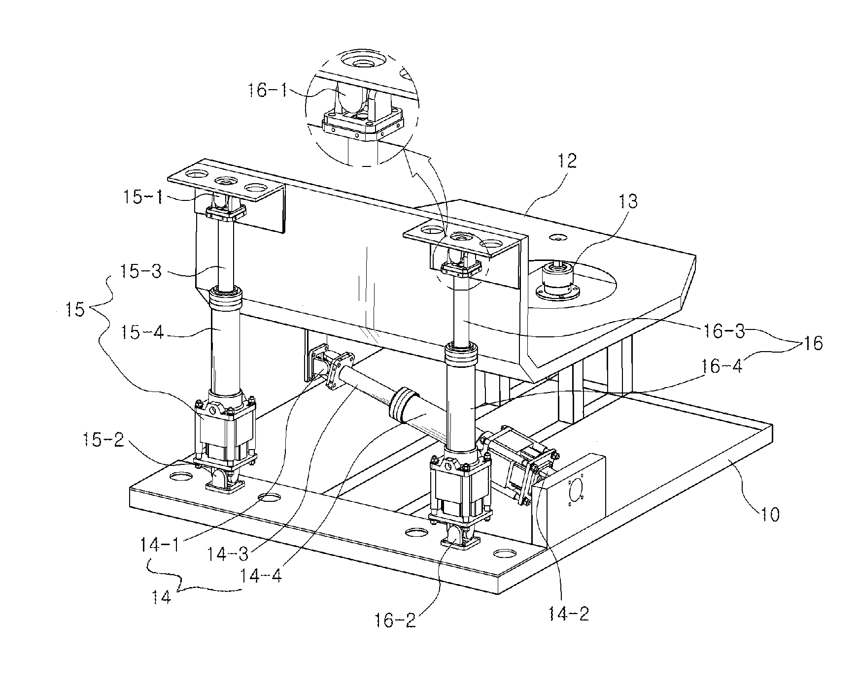
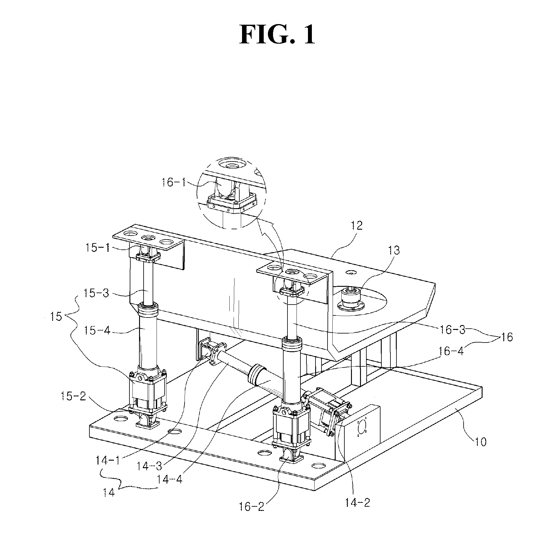
The present invention is about improving the stability of a motion simulator by adding a buffering unit to absorb shock during operation. This buffering unit can be a gas spring, gas shock absorber, or damper. This helps prevent the motion simulator from getting sideways or shaking during use, making it a more reliable and dependable product.

Problems solved by technology

Due to severe oscillation which occurs during rapid movement, the general simulator decreases in stability of an apparatus and a user may feel uncomfortable, thereby undermining the reliability of a product.

Method used


Image

  • Motion simulator
  • Motion simulator
  • Motion simulator

Examples


Embodiment Construction

[0020]Hereinafter, a configuration and operation of an exemplary embodiment of the present invention will be described in detail with reference to the attached drawings.

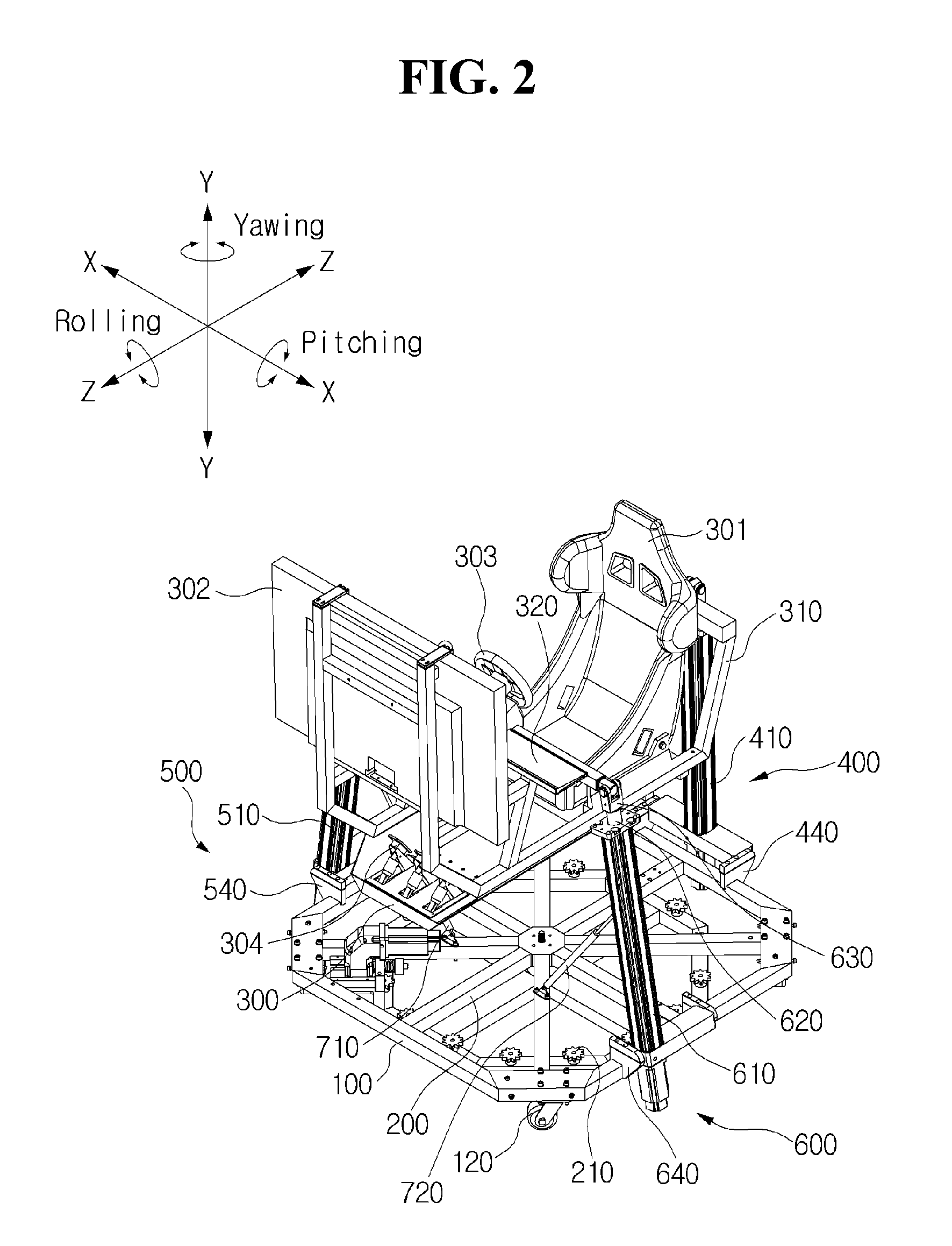
[0021]FIG. 2 is a perspective view of a motion simulator according to an embodiment of the present invention, and FIG. 3 is an exploded perspective view of a rotary plate 100 and a fixed plate 200 forming the motion simulator according to an embodiment of the present invention. Hereinafter, while describing a direction of a motion, as shown in FIG. 2, rolling is a rotary motion of rotating about a z axis which extends forward and backward, pitching is a rotary motion of rotating about an x axis which extends to the left and right, and yawing is a rotary motion of rotating about a y axis which extends up and down.

[0022]The motion simulator includes the rotary plate 100 with a motor 110 mounted on one side thereof and a plurality of casters 120 mounted on a bottom thereof, the fixed plate 200 which rotatably supports t...


PUM


Abstract

The objective of the present invention is to provide a motion simulator providing, to a link part, a buffering uniting part for absorbing impact during operation so as to prevent shaking of the motion simulator, thereby improving stability. To this end, the motion simulator of the present invention comprises: support members for supporting a chair on which a user sits, a monitor for providing images of a virtual environment according to the operation of the user, and a handle operated by the user for providing the virtual environment; and a plurality of link parts coupled to the lower portions of the support members so as to support the support members while simultaneously moving the same in the vertical direction, wherein at least one link part among the plurality of link parts are provided with buffering uniting parts for the absorption of impact.

Description

CROSS-REFERENCE TO RELATED APPLICATIONS[0001]This is a continuation of International Application No. PCT / KR2013 / 003089 filed on Apr. 12, 2013, which claims priority to Korean Application No. KR 10-2013-0018180 filed Feb. 20, 2013. The applications are incorporated herein by reference.TECHNICAL FIELD[0002]The present invention relates to a motion simulator, and more particularly, to a motion simulator which allows various simulation operations to be more stably performed using a simple structure.BACKGROUND ART[0003]Generally, motion simulators provide dynamic changes to fit in a virtual environment controlled by a computer, thereby allowing a user to feel movement in virtual reality as if it were real movement, and may not only be used for flight simulation or driving simulation but have also recently been used as simulators for a three-dimensional experience in games or movie theaters.[0004]Motion simulators perform a three-dimensional motion through a combination of a rectilinear m...

Claims


Application Information

Patent Timeline
Patent Type & Authority Applications(United States)
IPC IPC(8): F16M11/20G09B9/14A63G31/16G09B9/12
CPCF16M11/2035A63G31/16G09B9/14G09B9/12G09B9/00
Inventor KANG, YU SINLEE, JONG CHANCHUN, SANG GON
Owner MOTION DEVICE
Learn More