
Millimeter-Wave Dielectric Lens Antenna and Speed Sensor Using Same

a technology of dielectric lens and speed sensor, which is applied in the direction of using reradiation, instruments, and structural forms of radiating elements, can solve the problems of complex mounting adjustment of speed sensor attached to the frame, and achieve the effect of maximizing the gain of the lens antenna, improving the productivity of the sensor circuit board, and substantially maximizing the gain

Active Publication Date: 2015-12-03
HITACHI ASTEMO LTD
View PDF9 Cites 53 Cited by
  • Summary
  • Abstract
  • Description
  • Claims
  • Application Information

AI Technical Summary

Benefits of technology

The patent text describes a cannonball-shaped dielectric lens that helps to refract and parallelize radio waves from a point source in a waveguide or patch antenna array. By tilting the lens and aligning it with the waveguide's opening, the lens's radiation characteristics become maximized in the lens's inclination direction and the normal direction of the opening. This results in the highest radiationgain for the lens antenna. This feature can be utilized by combining one patch antenna with the inclination type cannonball-shaped lens, allowing the lens antenna to be directed at the maximum gain direction. This design simplifies the antenna's radiation characteristics, improves productivity, and reduces costs.

Problems solved by technology

Since a frontal projected area in the traveling direction increases so as to be equal to or greater than sin θ of an opening diameter of the lens, a problem of road clearance with the road surface may occur, or an air resistance coefficient of a Cd value may increase and mounting adjustment of a speed sensor which is attached to the frame may be expected to be complicated.

Method used


Image

  • Millimeter-Wave Dielectric Lens Antenna and Speed Sensor Using Same
  • Millimeter-Wave Dielectric Lens Antenna and Speed Sensor Using Same
  • Millimeter-Wave Dielectric Lens Antenna and Speed Sensor Using Same

Examples


embodiment 1

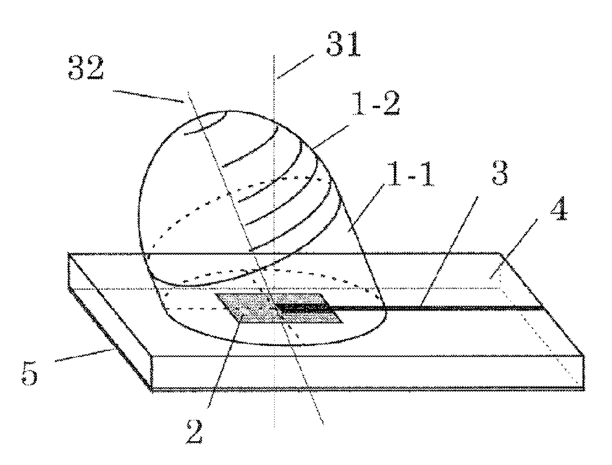
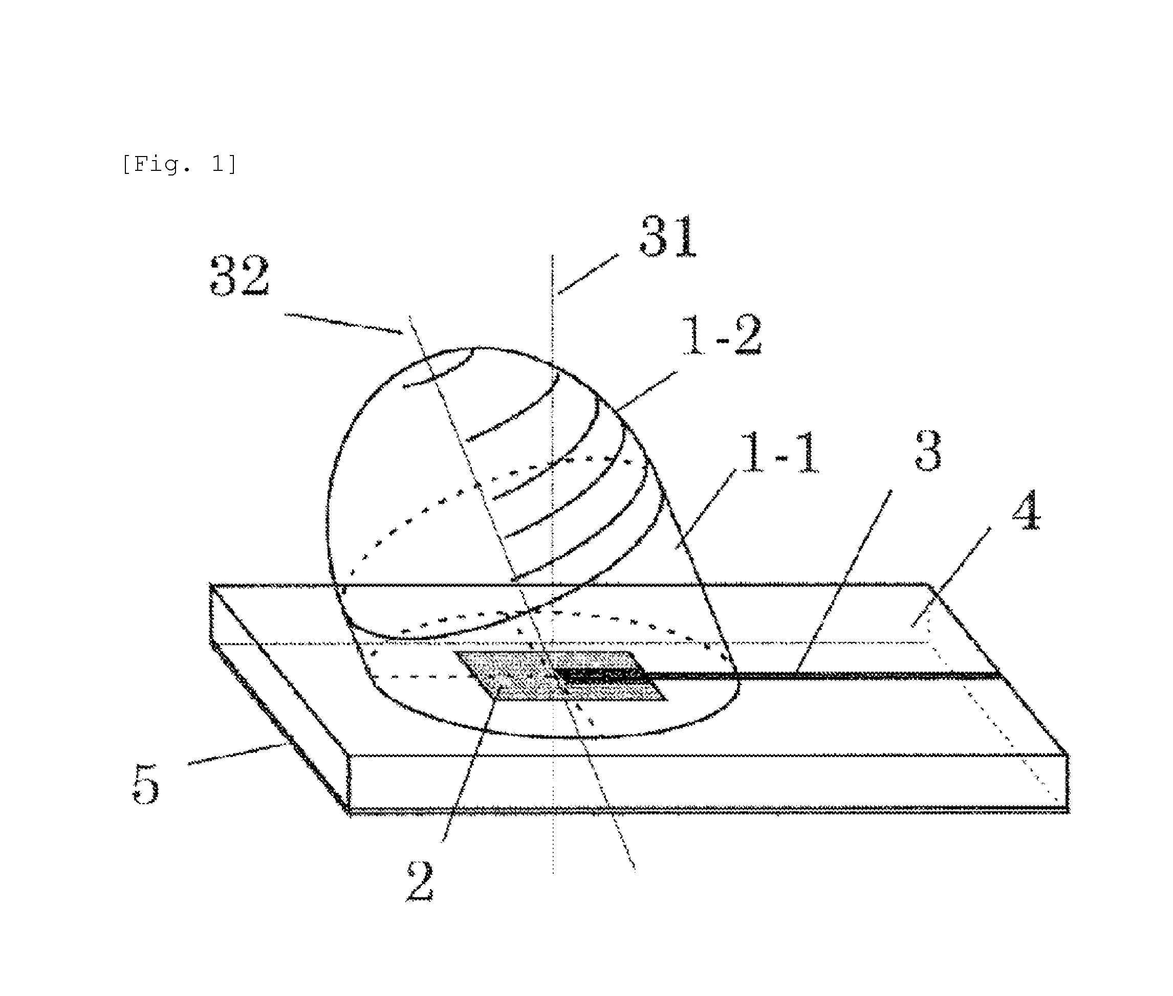
[0039]FIG. 1 is a perspective view of a dielectric lens antenna according to a first embodiment of the present invention. 1 indicates an inclination type cannonball-shaped dielectric lens. 2 indicates one patch antenna. 3 indicates a microstrip line. 4 indicates a mounted board. 5 indicates a GND electrode. The mounted board 4 uses an inorganic board which is formed of ceramics and the like, a single layer board of an organic board which is formed of glass epoxy resin and the like, and a multi-layer board obtained by alternately stacking the boards with a metallic thin film.

[0040]The one patch antenna 2 and the microstrip line 3 are formed on a surface of the mounted board 4. The GND electrode 4 is formed on a lower surface of the mounted board 4 as a facing electrode of the patch antenna and the microstrip line 3. The GND electrode has conductivity and functions to reflect a radio wave which is radiated from the patch antenna to the dielectric lens side.

[0041]A millimeter-wave sign...

embodiment 2

[0056]FIG. 5 is a side view of a dielectric lens antenna of a first example according to a second embodiment of the present invention. 1 indicates an inclination type cannonball-shaped dielectric lens. 2 indicates one patch antenna. 4 indicates a mounted board. 6 indicates a second dielectric lens.

[0057]The second dielectric lens is a unilateral convex surface lens or a dual-sided convex surface lens. The second dielectric lens uses a dielectric lens having a large opening area in order to much more condense a millimeter radio wave which is radiated from the inclination type cannonball-shaped dielectric lens 1.

[0058]FIG. 6 is a side view of a dielectric lens antenna of a second example according to a second embodiment of the present invention. Generally, a radio wave which passes through an optical axis of a lens travels straight without refraction. A radiation direction of beams may be much more inclined using refraction by causing the millimeter radio wave which is radiated from t...

embodiment 3

[0067]FIG. 11 is a perspective view of a speed sensor of a first example according to a third embodiment of the present invention.

[0068]1 indicates an inclination type cannonball-shaped dielectric lens, 2 indicates one patch antenna, 4 indicates a mounted board, 11 indicates a millimeter-wave band RF circuit, and 12 indicates an Analog / Digital Converter (ADC) or a Digital / Analog Converter (DAC). 13 indicates a Digital Signal Processing Unit (DSP) and 14 indicates a Power Unit.

[0069]FIG. 12 is a circuit configuration diagram of the speed sensor illustrated in FIG. 11. A millimeter-wave signal which is generated by the RF circuit portion 11 is radiated from a Tx / Rx antenna 15 which is formed from the dielectric lens 1 and the one patch antenna. The radiated signal reaches and is reflected by a measurement object which is a target. The reflected signal is received by the Tx / Rx antenna 15 again.

[0070]The received millimeter-wave signal includes a Doppler signal by a difference in a rela...


PUM


Abstract

A speed sensor which aligns a normal direction of one patch antenna which is disposed on a mounted board, and an optical axis of a dielectric lens uses a frame for inclining a sensor module, in order to obtain a component cos θ in a traveling direction when the speed sensor is installed on a horizontally vertical surface of an automobile or a railway car. When beams are condensed by using the one patch antenna and the cannonball-shaped dielectric lens, the dielectric lens is inclined and a bottom surface portion of the lens is cut with a plane parallel with a surface of the antenna-mounted board. The one patch antenna is configured by one patch and a GND electrode and the gain center of radiation characteristics is a normal direction of the antenna board. However, the radiation characteristics have a substantially hemisphere surface wave shape.

Description

TECHNICAL FIELD[0001]The present invention relates to a speed sensor that performs reflection response measurement through the Doppler effect by using an electromagnetic wave of a millimeter wave band.BACKGROUND ART[0002]A speed sensor is used as a speed measurement device of a moving object such as an automobile and a train in order to understand a motion circumstance of a target object. In a general moving object which moves by wheels or the like, a relative velocity is measured by measuring an angle of a rotation axis.[0003]Frictional resistance by a surface state of a medium is applied at a contact portion of a road surface with a wheel and the like and thus a relative speed to the road surface without spinning may be measured.[0004]However, an axial torque of a rotating object is greater than the frictional resistance in a low-p road which has a low frictional coefficient (mu (μ)) and the rotating object such as a wheel is in a state of easily sliding. Thus, it is impossible to...

Claims


Application Information

Patent Timeline
Patent Type & Authority Applications(United States)
IPC IPC(8): G01S13/60H01Q1/38H01Q1/42H01Q15/08
CPCG01S13/60H01Q1/421H01Q1/38H01Q15/08G01S7/025G01S7/03G01S13/87G01S7/027H01Q1/42H01Q19/09
Inventor NAGAISHI, HIDEYUKIMATSUMURA, TAKAFUMI
Owner HITACHI ASTEMO LTD
Learn More