
Viable particle counting system and viable particle counting method

Active Publication Date: 2015-12-03
RION COMPANY
View PDF3 Cites 18 Cited by
  • Summary
  • Abstract
  • Description
  • Claims
  • Application Information

AI Technical Summary

Benefits of technology

The invention allows for very precise counting of very small particles that only emit weak fluorescence. This is possible by irradiating the particles with UV light before counting them using a special counter. The result is a better signal-to-noise ratio and increased accuracy in the counting of the viable particles.

Problems solved by technology

It is therefore difficult to detect only the presence or absence of viable particles using autofluorescence as an index for detection.
Accordingly, it is difficult to detect the presence or absence of viable particles according to the foregoing related art.
In addition, viable particles of fungi emitting feeble autofluorescence, such as heterotrophic bacteria, may not be detected by a viable particle counter using detection of autofluorescence as an index.

Method used


Image

  • Viable particle counting system and viable particle counting method
  • Viable particle counting system and viable particle counting method
  • Viable particle counting system and viable particle counting method

Examples


example 1

[0126]Of the four kinds of fungi, the large-sized white colony denoted by (A) in FIG. 11 was put into the water in the beaker and stirred there. The water was irradiated with ultraviolet light (UV-C) from the ultraviolet lamp, and the viable particles in the water were counted by the viable particle counter 77 after each irradiation time. Specifically, the inventors have confirmed the transition between the counted values corresponding to autofluorescence obtained with processing output signals from photo multiplier which received autofluorescence and the counted values corresponding to scattered light obtained with processing output signals from photo diode which received scattered light.

[0127]FIG. 12 is a graph representing the correlation between autofluorescence counted value for irradiation time of ultraviolet light and scattered light counted value for irradiation time of ultraviolet light concerning fungi forming a large-sized white colony (A).

[0128]The lateral axis in FIG. 1...

example 2

[0134]FIG. 13 is a graph representing the correlation between autofluorescence counted value for irradiation time of ultraviolet light and scattered light counted value for irradiation time of ultraviolet light concerning fungi forming a medium-sized red colony (B).

[0135]The lateral axis, the longitudinal axis, and the curve lines in the graph are the same as those in FIG. 12 described above, and descriptions thereof will be omitted (the same is applicable to FIGS. 14 and 15).

[0136]As illustrated in FIG. 13, before the irradiation of ultraviolet light (UV-C) by the ultraviolet lamp (0 mm), the counted value of the scattered light (scattered CUMU) was about 10000 (particles / 10 ml), whereas the counted value of the autofluorescence (fluorescence CUMU) was about 7000 (particles / 10 ml). Therefore, considering that the counted value of the scattered hat was obtained by detection of light emitted from all of the viable particles, autofluorescence could not be detected from some of the par...

example 3

[0140]FIG. 14 is a graph representing the correlation between autofluorescence counted value for irradiation time of ultraviolet light and scattered light counted value for irradiation time of ultraviolet light concerning fungi forming a medium-sized yellow colony (C).

[0141]As illustrated in FIG. 14, before the irradiation of ultraviolet light (UV-C) by the ultraviolet lamp (0 min), the counted value of the scattered light (scattered CUMU) was about 16500 (particles / 10 ml), whereas the counted value of the autofluorescence (fluorescence CUMU) was about 2000 (particles / 10 ml). Therefore, considering that the counted value of the scattered light was obtained by detection of light emitted from all of the viable particles, the autofluorescence was hardly detected, which means that the actual number of the viable particles could not be counted.

[0142]With increase in the irradiation time of ultraviolet light (UV-C) from the ultraviolet lamp, the counted value of the autofluorescence (fluo...


PUM


Abstract

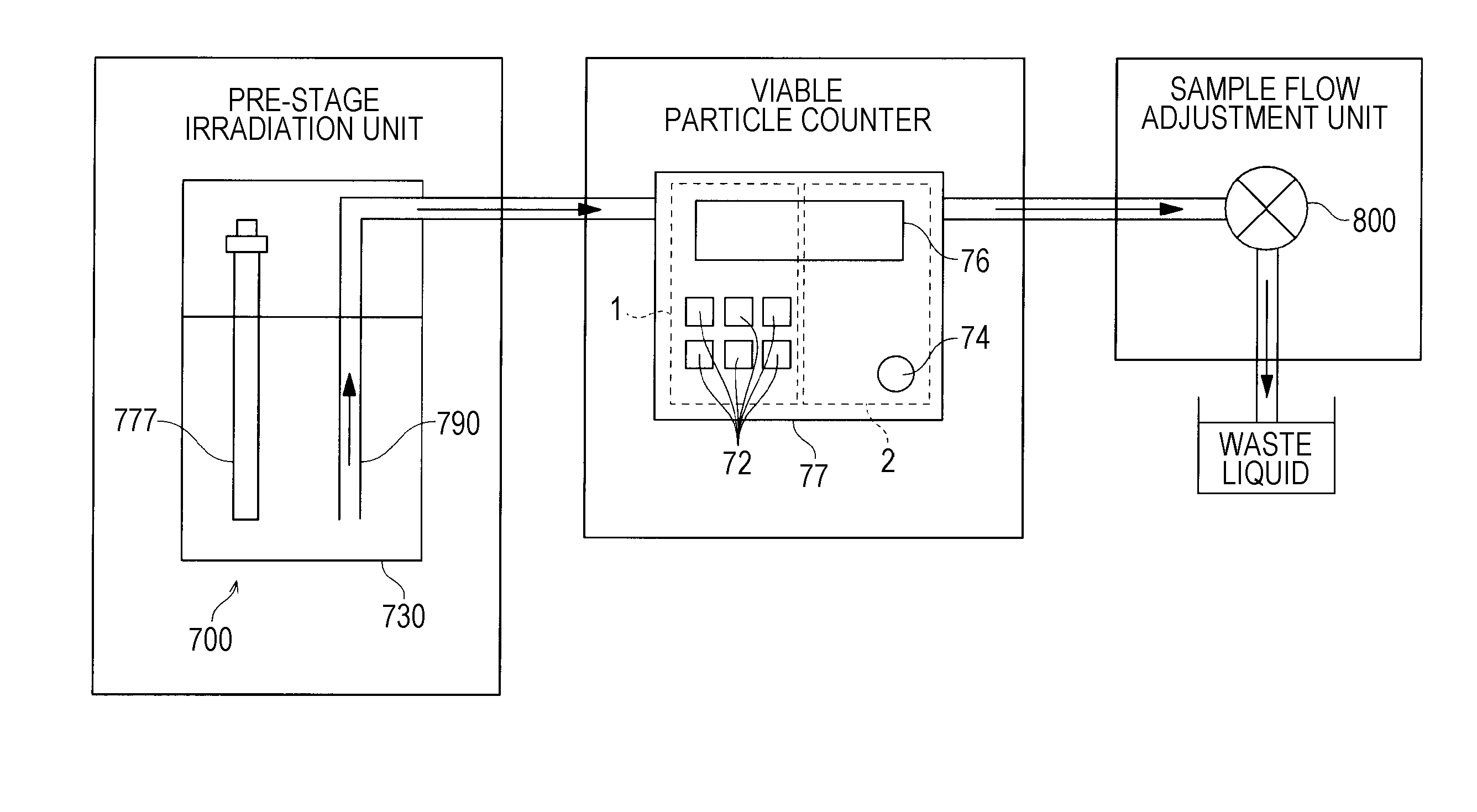
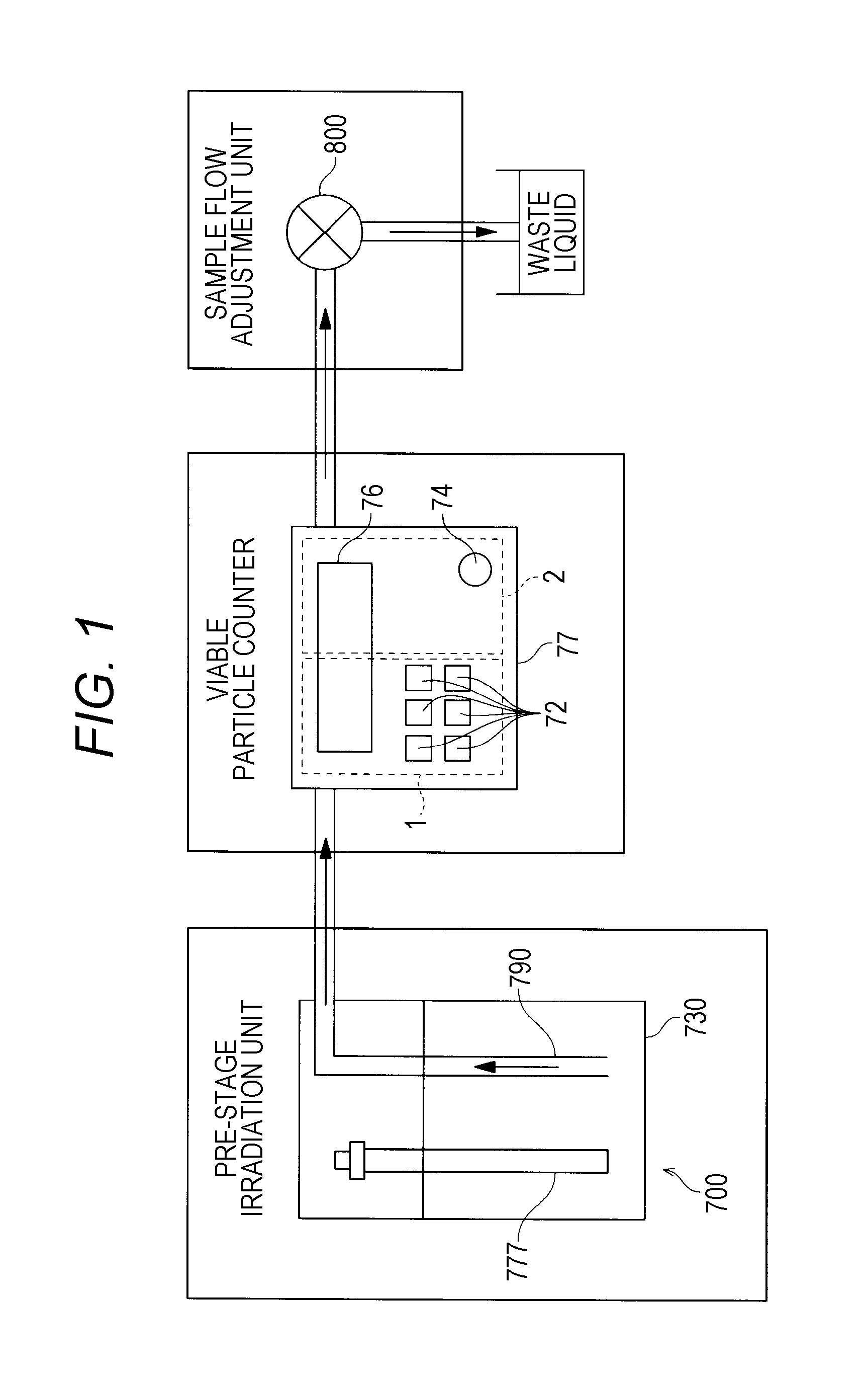
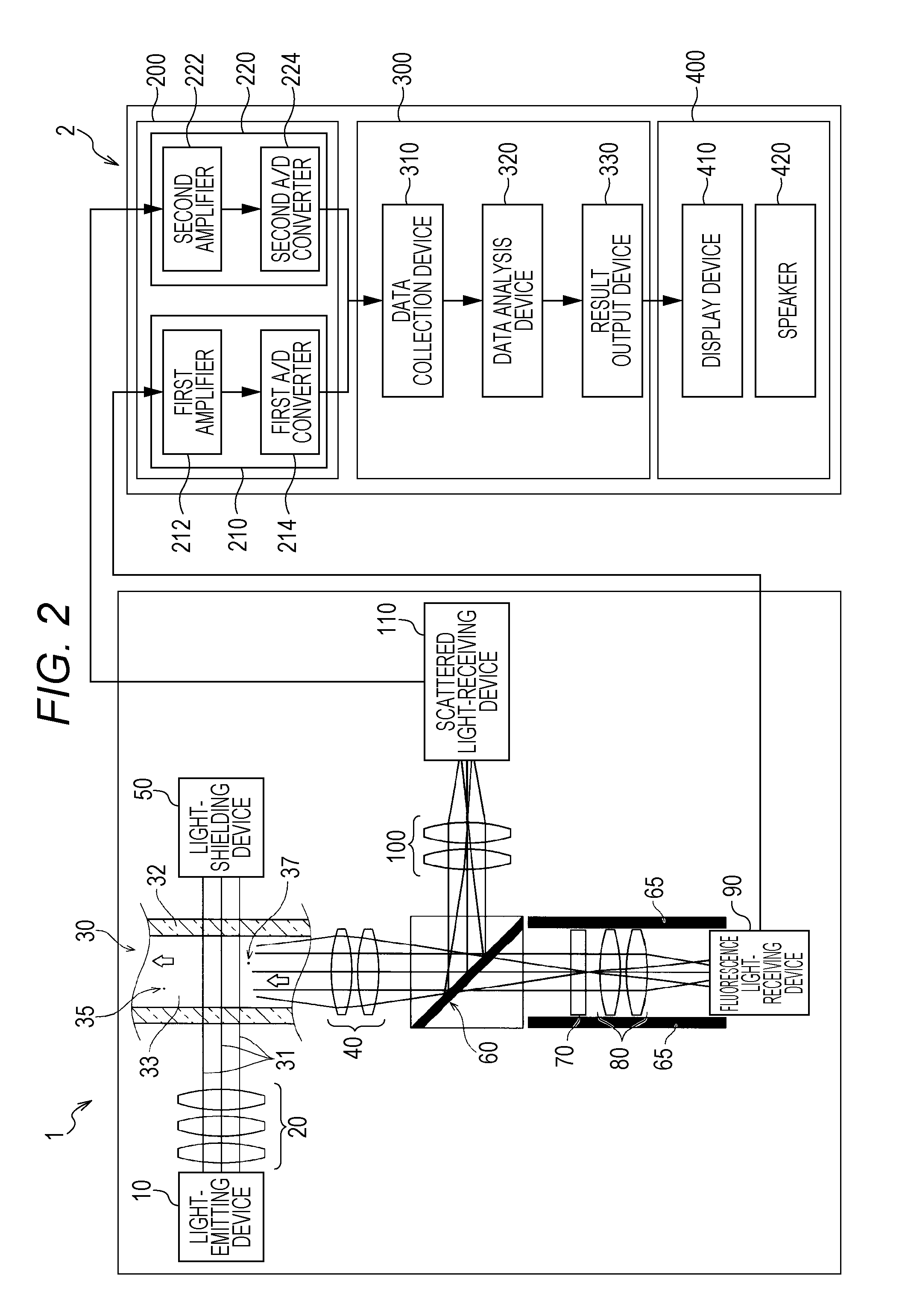
This invention relates to a viable particle counting system. The system includes: a viable particle counting means that counts viable particles existing in a fluid by irradiating the fluid containing target particles to be detected with light at a predetermined wavelength, separating selectively autofluorescence or phosphorescence emitted from the target particles by the radiated light, receiving the separated autofluorescence or phosphorescence, and determining that the target particles are the viable particles according to the received autofluorescence or phosphorescence; and a pre-stage irradiation means that irradiates the fluid with ultraviolet light in advance before the viable particle counting means irradiates the fluid with the light at the predetermined wavelength.

Description

CROSS REFERENCE TO RELATED APPLICATIONS[0001]The present application is the U.S. National Phase of International Patent Application Serial No. PCT / JP2014 / 000,252, filed Jan. 20, 2014, which claims priority to Japanese Patent Application Serial No. 2013-023189, filed Feb. 8, 2013. The contents of the foregoing applications are incorporated by reference in their entireties.TECHNICAL FIELD[0002]This invention relates to a viable particle counting system and a viable particle counting method that are configured to detect viable particles in the air or a liquid according to autofluorescence or phosphorescence emitted from the viable particles.BACKGROUND ART[0003]There are conventionally known methods for detection of viable particles such as a cultivation method (official method), a microcolony method, an ATP (luciferase) method, a fluorescent dye method, and an autofluorescence method. Among these detection methods, the autofluorescence method makes it possible to obtain the result on t...

Claims


Application Information

Patent Timeline
IPC IPC(8): G01N15/14G01N21/64
CPCG01N15/1436G01N15/1459G01N2021/6482G01N21/645G01N2015/1486G01N15/1404G01N21/05G01N21/64G01N2015/1493G01N21/53G01N2021/6471G01N2021/6493G01N33/1826G01N21/6486G01N2015/019
Inventor SEKIMOTO, KAZUMA
Owner RION COMPANY
Learn More