
Surface texture of light guide plate, use and manufacturing method thereof

Inactive Publication Date: 2015-11-26
ZHANG DAHAI
View PDF14 Cites 27 Cited by
  • Summary
  • Abstract
  • Description
  • Claims
  • Application Information

AI Technical Summary

Benefits of technology

The present invention is a light guide plate with a surface texture that has the advantage of reducing specular reflection and achieving optically smooth surfaces. The texture of the light guide plate also meets the requirement of total reflection, ensuring that the working light will not escape from the plate. This results in a light guide plate with good anti-reflective performance and a product with reduced reflectivity.

Problems solved by technology

The specular reflection of the mirror surface can generates mirror images of surroundings, such as windows and fluorescent tubes, some mirror images result in glare and reflection.
The clear and bright mirror images mix with the handwriting, which seriously interferes with viewer's visual identification of the content on the blackboard.
The higher the clarity of the mirror images, the higher the brightness, and the interference to the visual identification is more serious.
The specular reflection seriously interferes with viewer's visual identification of the content on the blackboard, which makes the comfort of the use of the lighting blackboard reduced.
Using the lighting blackboard for a long time has bad effects on viewer's vision, such as asthenopia, even worse effects, such as vertigo.
The lighting blackboards disclosed by those applications are common lighting blackboards based on the classical light guide plate, and have the disadvantage of the specular reflection interference.
It has been nearly 20 years since the common lighting blackboard was advanced, the market of the lighting blackboard applied on advertisements propaganda has been formed a certain scale, however, the lighting blackboard has been not able to come into the field of education and class.
However, the cost of this way is expensive, and the anti-reflective layer is fragile and easy to be damaged.
In addition, the anti-reflective layer is easy to lose efficacy for slightly pollution of the layer, therefore, the layer isn't suitable for use in the field of lighting blackboards.
When a rough surface is applied on the surface of the light guide plate, the total reflection requirement of the light guide plate can't be met, the rough area appears to be lighting, so that the rough surface can't be applied on the field of lighting blackboards.

Method used


Image

  • Surface texture of light guide plate, use and manufacturing method thereof
  • Surface texture of light guide plate, use and manufacturing method thereof
  • Surface texture of light guide plate, use and manufacturing method thereof

Examples


first embodiment

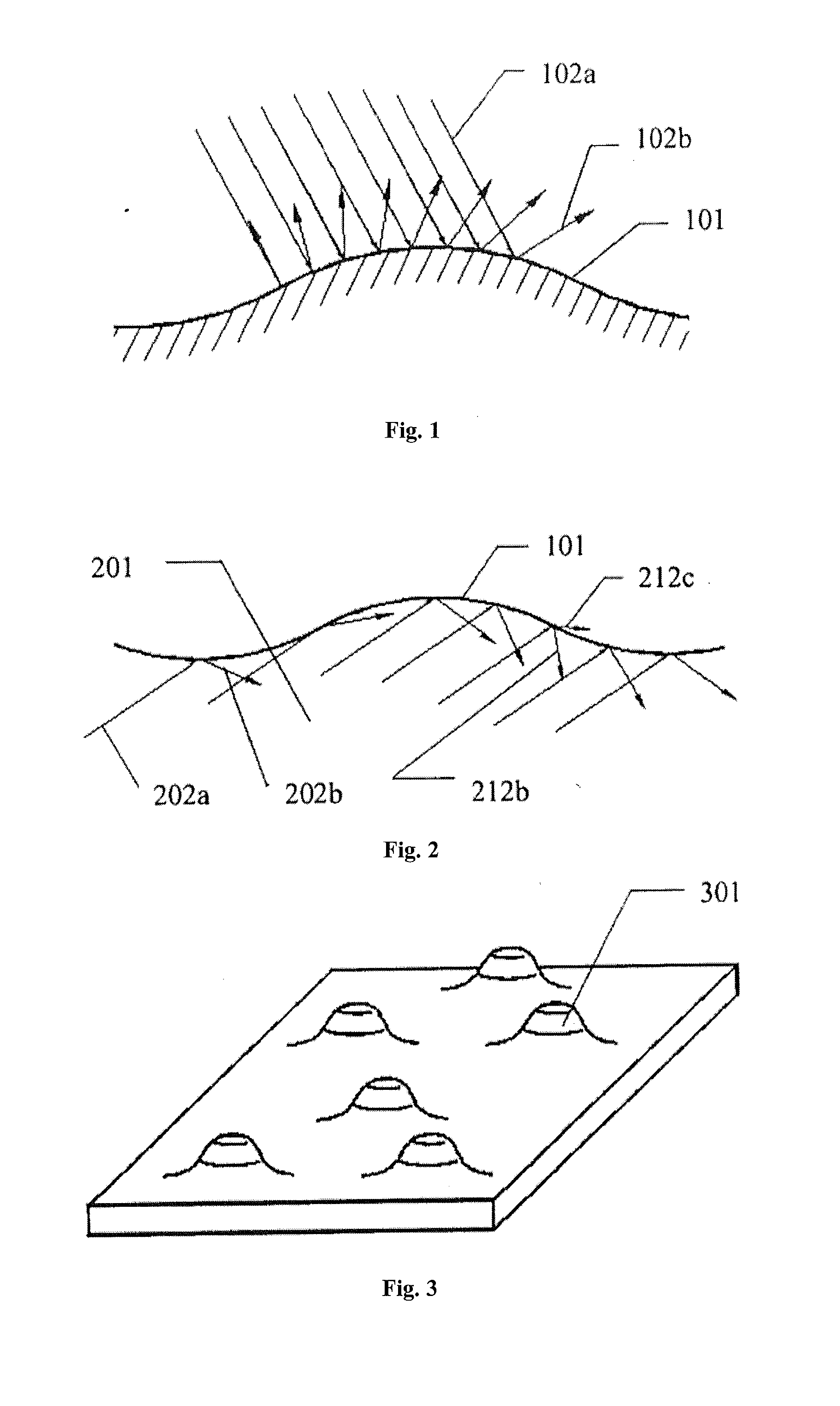
[0074]FIG. 3 shows the convex-concave structures, particularly shows the appearance of hill-like protrusions 301 with optically smooth surfaces. The hill-like protrusions are generated on a surface of a transparent medium. The convex-concave structures are hill-like in shape, just like independent small hills. The outer surface of the hill-like protrusion is optically smooth, the mean deviation of the roughness profiles of the outer surface isn't greater than ⅛ the shortest wavelength of the working light.

[0075]The hill-like protrusions can be generated by printing transparent glue points on the surface through inkjet printing and then solidifying the glue points by ultraviolet light. Also, injection molding or other methods can be used for molding the protrusions. 3D printers can also be used for molding.

[0076]Embodiment of Surface Texture 2:

second embodiment

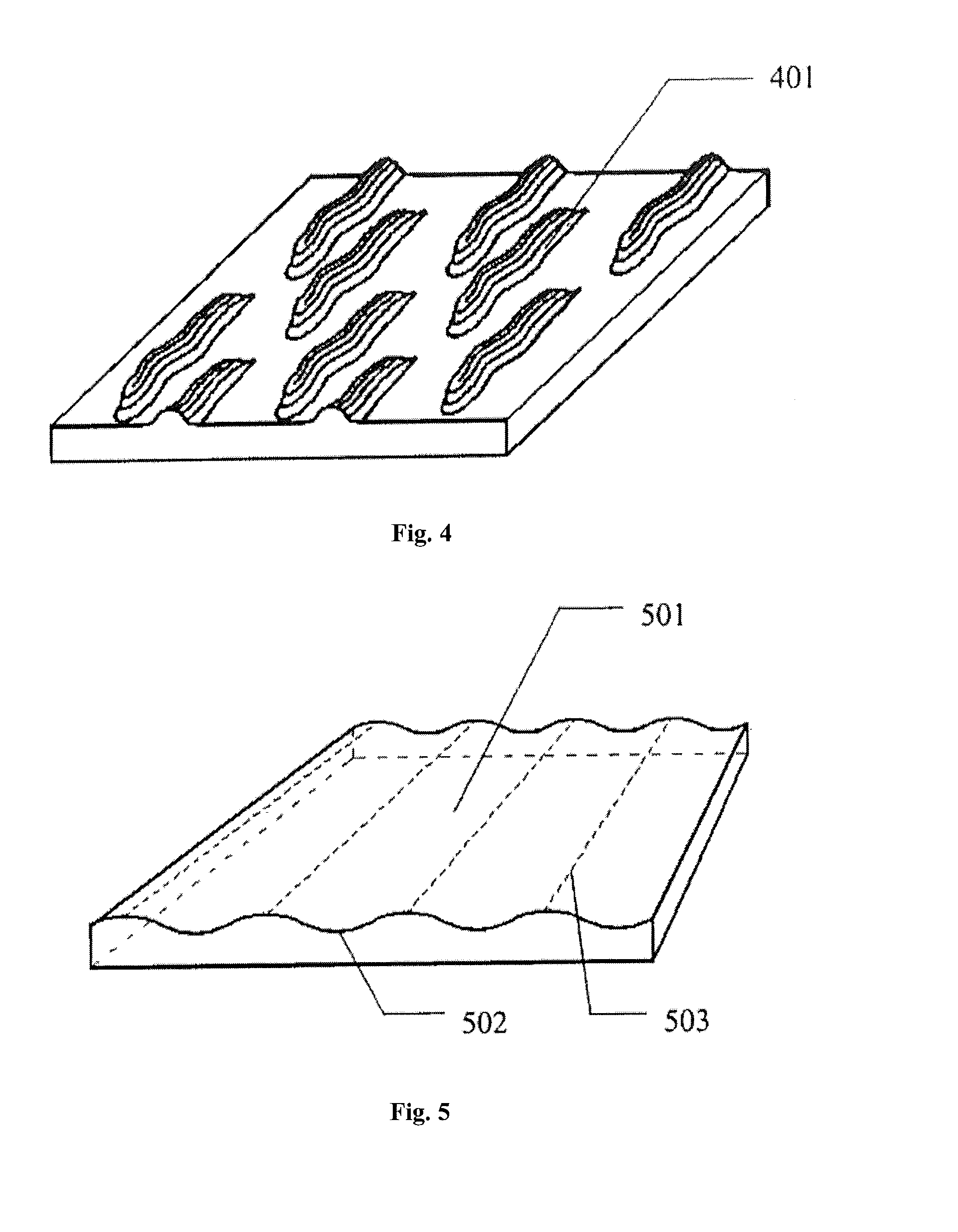
[0077]FIG. 4 shows the convex-concave structures, particularly shows the appearance of strip convex-concave structures with smooth surfaces. The convex-concave structures are strip-shaped, just like extending mountain ridges. The surfaces of the strip convex-concave structures are optically smooth. When the working light is white light, the mean deviation of the roughness profiles of the structure is required to be not greater than 50 nanometers.

[0078]The strip convex-concave structure 401 is a slightly curved strip, in other cases the structure can also be a straight strip, a curved strip and a strip with more complex structure. The curved strip can be C-shaped, Y-shaped, or even O-shaped, it will not be described in detail here. The straight strip and the slightly curved strip are commonly used.

[0079]Generally, a extending direction along a long dimension of the strip convex-concave structure can be referred as a longitudinal direction, the direction perpendicular to the longitudi...

third embodiment

[0081]FIG. 5 shows the convex-concave structure, particularly shows the appearance of wave convex-concave structures with smooth surfaces.

[0082]In this embodiment, convex and concave circular arcs forms a circular arc wave line 502 which acts as a guide line of a circular arc wave surface 501, a straight line acts as a wave surface generatrix 503. The surfaces of the wave convex-concave structures are optically smooth.

[0083]The wave lines include but not limit to regular curves, such as circular arc wave lines, elliptic wave lines, sine wave lines, parabola wave lines, and one of or combination of randomly changed irregular wave lines.

[0084]In particular, FIG. 6 illustrates different kinds of wave lines which can act as a guide line.

[0085]The elliptic wave line 6a is formed by connecting convex elliptic arcs with concave elliptic arcs in sequence.

[0086]The sine wave line 6b is a continual sine curve.

[0087]The irregular wave line 6c is a wave line drawn randomly.

[0088]Different kinds...


PUM


Abstract

A surface texture of a light guide plate (101), use and manufacturing method thereof, wherein the surface texture includes convex-concave structures (301, 401, 501), the curved surfaces of the convex-concave structures are optically smooth, the arithmetical mean deviation of the surface roughness profiles isn't greater than ⅛ shortest wavelength of working light in the light guide plate. By using the light guide plate with the surface texture, not only can total reflection be performed in the light guide plate, but also the outer surface of the light guide plate appears to have the effect similar to diffuse reflection, so that specular reflection of the surface of the classical light guide plate can be overcome.

Description

BACKGROUND OF THE INVENTION[0001]1. Technical Field[0002]The invention relates to the field of light guides, and more particularly, to a surface texture of a light guide plate, a light guide plate with the surface texture, a product using the light guide plate and a manufacturing method of the surface texture.[0003]2. Description of Related Art[0004]A light guide is an optical constituent by which light can be transmitted with very low reflection loss through the total reflection of the inner surface of a medium. Generally, the light guides are divided into two categories: planar light guides and fiber light guides. A plane light guide plate is a typical planar light guide, and can be referred to as a light guide plate for short. Plane glass in vacuum or air is the simplest light guide plate.[0005]When light travels in the light guide plate, the light can be transmitted without reflection loss substantially through total reflection if the light meets the requirement of the total ref...

Claims


Application Information

Patent Timeline
IPC IPC(8): F21V8/00B43L1/10
CPCG02B6/0036B43L1/10G02B6/0038G02B6/0035G02F1/133615
Inventor ZHANG, DAHAIYANG, YANPING
Owner ZHANG DAHAI
Learn More