
Condenser for refrigerator

a technology for condensers and refrigerators, applied in refrigeration components, indirect heat exchangers, lighting and heating apparatus, etc., can solve the problems of increasing the interior temperature reducing the volume of the usable inner space of the refrigerator proportional to the size of the machine room, etc., and achieving the effect of preventing the trapping of dus

Inactive Publication Date: 2015-11-12
SAMWON IND
View PDF13 Cites 14 Cited by
  • Summary
  • Abstract
  • Description
  • Claims
  • Application Information

AI Technical Summary

Benefits of technology

The present invention aims to solve the problems of existing condensers for refrigerators. It provides a condenser with fin structures that have wider width than the tubes, which increases the heat exchange range and efficiency. The fin structures and tubes have a U-shaped form, which saves space and improves heat exchange. The fins are longitudinally corrugated with a pitch between 2 mm to 10 mm to prevent dust trapping. Overall, the invention improves the performance of refrigerators' condensers.

Problems solved by technology

However, conventional condensers or evaporators have limits to increase a heat radiation area and, consequently, to enhance heat radiation efficiency and heat exchange efficiency.
However, due to fact that both the compressor and the condenser are mounted in the machine room, the machine room as described above occupies almost all of a bottom region of the refrigerator, which causes a reduction in the volume of a usable inner space of the refrigerator proportional to the size of the machine room.
While the machine room cover has slits to allow interior heat of the machine room, i.e. heat of the compressor, heat of the refrigerant radiated around the condenser, and the like to be discharged outward, these slits of the machine room cover do not provide rapid heat radiation from the machine room, which inevitably causes increase in the interior temperature of the machine room.

Method used


Image

  • Condenser for refrigerator
  • Condenser for refrigerator
  • Condenser for refrigerator

Examples


Embodiment Construction

[0033]Hereinafter, embodiments of the present invention will be described in detail with reference to the accompanying drawings to enable easy implementation of the present invention by those skilled in the art. However, the present invention may be embodied as various different schemes, and should not be limited to the embodiments described herein. Throughout the specification, the same reference numerals designate the same or similar parts.

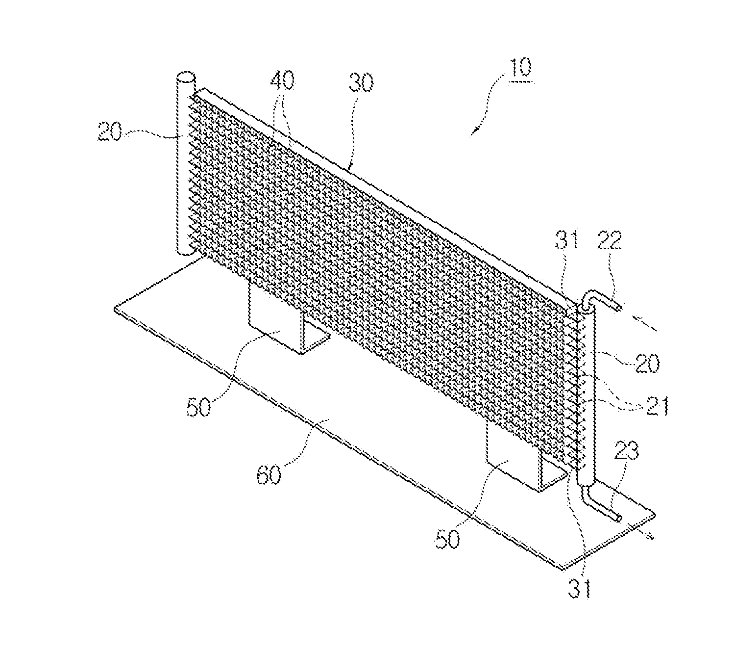
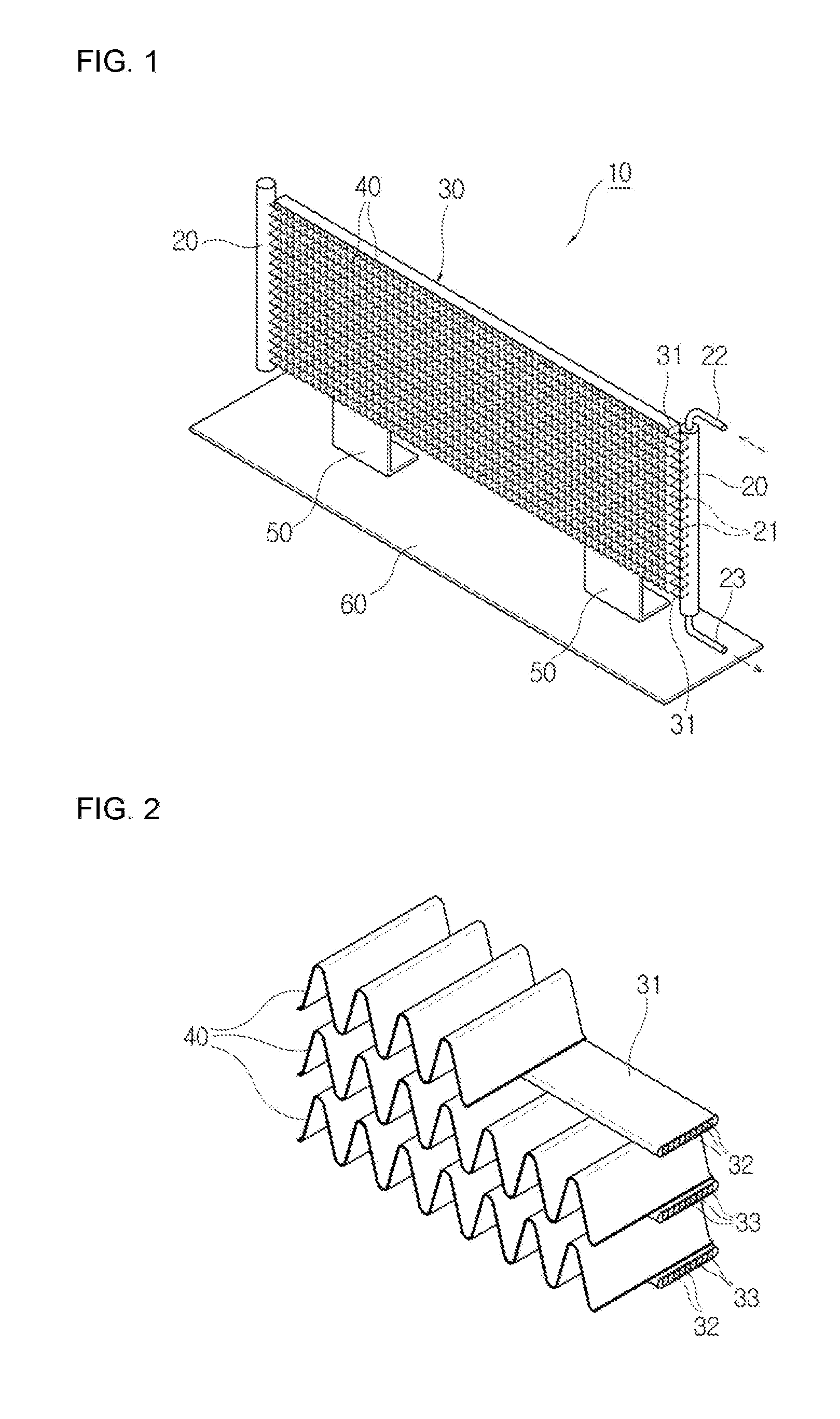
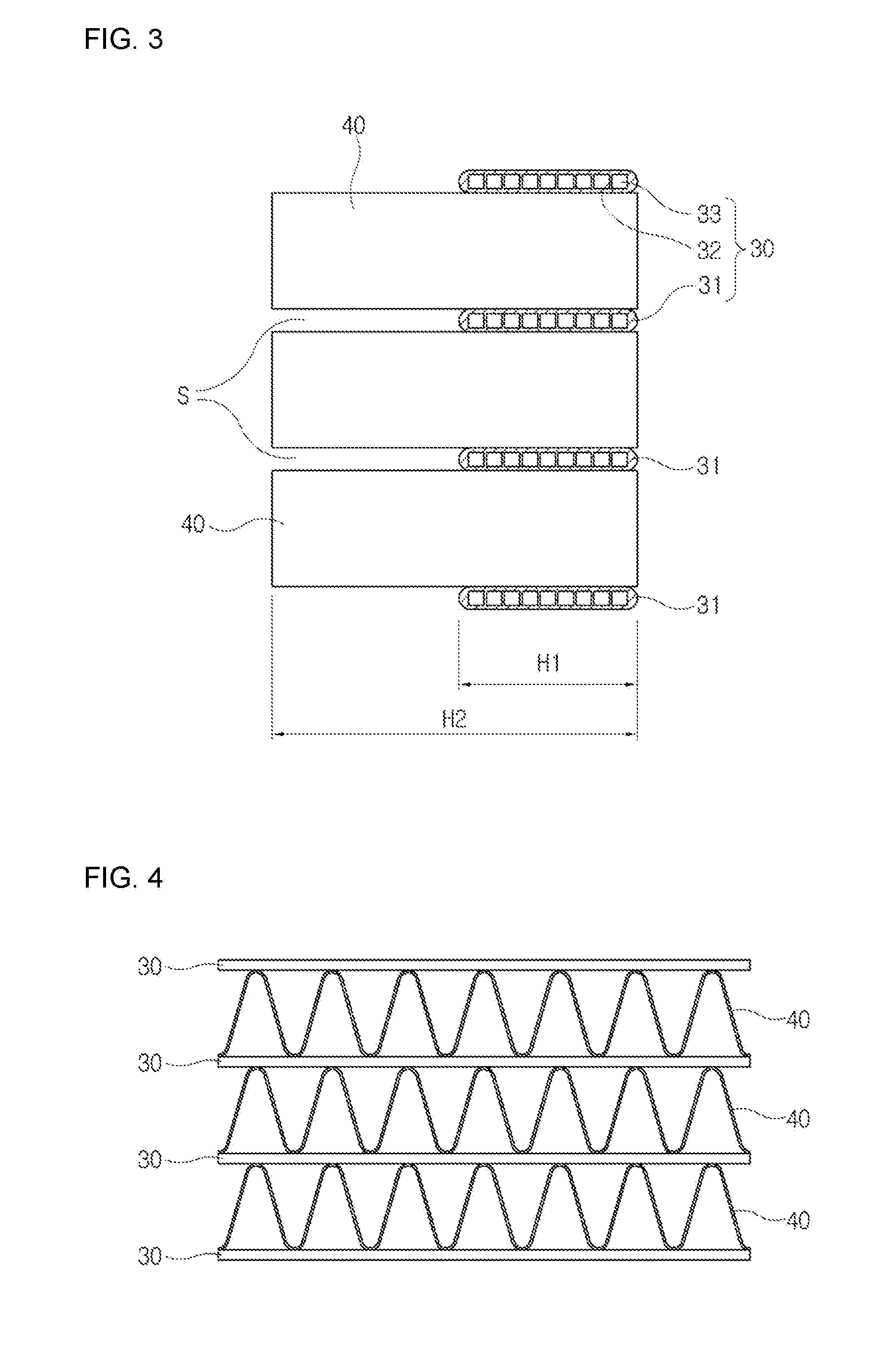
[0034]Explaining a configuration of the present invention below with reference to the accompanying drawings, FIG. 1 is a perspective view showing a condenser for refrigerator according to the present invention, FIG. 2 is a perspective view showing a tube unit and fin structures included in the condenser for refrigerator according to the present invention, and FIGS. 3 and 4 are respectively a side view and a front view showing the tube unit and the fin structures included in the condenser for refrigerator according to the present invention.

[0035]...


PUM


Abstract

A condenser for refrigerator includes left and right or upper and lower headers spaced apart from each other for introduction or discharge of refrigerant, a tube unit including tubes mounted between the headers and spaced apart from one another to allow the refrigerant to pass through the tubes, and a fin structure mounted in the respective neighboring tubes to perform heat exchange between the refrigerant passing through the tubes and outside air, the fin structure including fins having a greater width than a width of the tubes. Providing the fins with a greater width than that of the tubes may achieve an expanded heat exchange range and higher heat exchange efficiency. Moreover, wider gaps between the fins ensure smooth air movement, causing a reduced pressure difference of the moving air and neither dust nor debris is trapped between the fins, resulting in higher heat exchange efficiency.

Description

CROSS REFERENCE[0001]This application claims foreign priority under Paris Convention to Korean Patent Application Nos. 10-2014-0055718, filed 9 May 2014, and 10-2014-0055690, filed 9 May 2014, respectively with the Korean Intellectual Property Office, which are incorporated herewith in its entirety.BACKGROUND[0002]The present invention relates to condenser for refrigerator and, more particularly, to condenser for refrigerator in which fins have a greater width than a width of tubes, which may result in an expanded heat exchange range and higher heat exchange efficiency and ensure easy installation of the condenser even in a narrow space and efficient implementation of heat exchange.[0003]Generally, refrigerators include a refrigeration cycle that is comprised of a compressor, a condenser, a capillary tube, an evaporator, and the like for sequential circulation of refrigerant. The compressor compresses gas-phase refrigerant into high temperature and high pressure gas-phase refrigeran...

Claims


Application Information

Patent Timeline
IPC IPC(8): F25B39/00
CPCF25B39/04F25B39/00F28D1/047F28D1/0535F28F1/126F28D2021/0084
Inventor KIM, KAPYOUNGKIM, YOUNGJIN
Owner SAMWON IND
Learn More