
Laser deposition of metal foam

a metal foam and laser technology, applied in the field of material technology, can solve the problems of extremely limited commercial use of metal foam in the power generation field

Inactive Publication Date: 2015-11-12
SIEMENS ENERGY INC
View PDF35 Cites 30 Cited by
  • Summary
  • Abstract
  • Description
  • Claims
  • Application Information

AI Technical Summary

Benefits of technology

The present invention relates to a layer of metal foam that can be deposited on a gas turbine component surface. This foam layer has several advantages. Firstly, it can provide better resistance to thermo-mechanical fatigue and cracking, due to its flexible and crack-resistant nature. Secondly, it can improve resilience to foreign object damage. Finally, it can improve cooling when formed along a cooling channel surface, reducing or eliminating the need for drilled cooling holes.

Problems solved by technology

In spite of a large number of patents describing metal foams, their commercial use in the power generation field has been extremely limited due to the difficulty of manufacturing such materials in commercially practical forms.

Method used


Image

  • Laser deposition of metal foam
  • Laser deposition of metal foam

Examples


Embodiment Construction

[0009]The present inventors have recognized a need for an improved method of manufacturing metal foam, particularly for manufacturing superalloy metal foam material that may be suitable for use in fabricating hot gas path components for gas turbine engines.

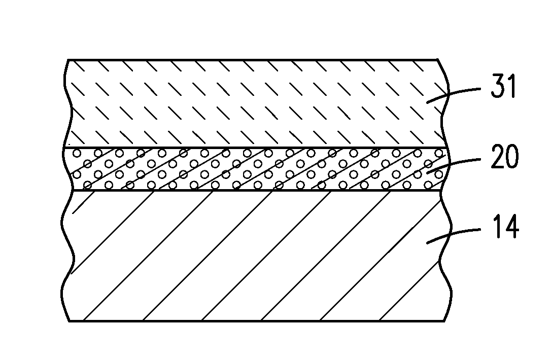
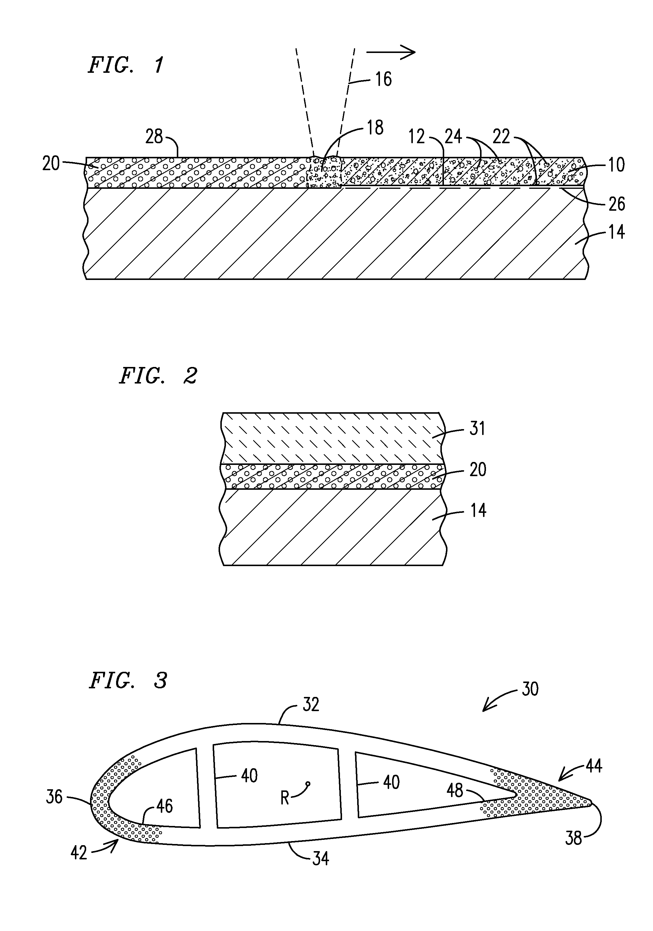
[0010]FIG. 1 illustrates an embodiment of such an improved method, wherein a powder mixture 10 deposited onto a surface 12 of a substrate 14 is melted with an energy beam 16 to form a melt pool 18, which then is allowed to solidify to form a layer of metal foam 20 on the substrate 14. The powder mixture 10 includes particles of metal 22 and particles of a foaming agent 24.

[0011]The term “metal” is used herein in a general sense to include both pure metals and metal alloys, and in the embodiment of FIG. 1, the substrate 14 and the particles of metal 22 are a superalloy material such as may be used in a gas turbine engine application, for example the materials sold under the trademarks or brand names IN 700, IN 939, Rene 80, CM 247,...


PUM

PropertyMeasurementUnit
Compositionaaaaaaaaaa
Viscosityaaaaaaaaaa
Electrical resistanceaaaaaaaaaa

Abstract

A layer of superalloy metal foam (20) is deposited onto a superalloy substrate (14) by laser melting (16) a powder mixture (10) containing particles of a superalloy metal (22) and particles of a foaming agent (24). A gas turbine engine component (30) is formed to include such metal foam. A ceramic thermal barrier coating material (31) may be applied directly over the metal foam without an intervening bond coat layer.

Description

FIELD OF THE INVENTION[0001]This invention relates generally to the field of materials technology, and more specifically to methods of forming metal foams and components formed thereof.BACKGROUND OF THE INVENTION[0002]Metal foams are cellular structures including a large volume fraction of pores. While most metal structures contain some porosity, for example a few volume percent, metal foams may typically contain at least 75% volume fraction of pores.[0003]Metal foams can be formed in several ways: by injecting gas into molten metal; by forming gas in-situ in molten metal through a chemical reaction; by lowering pressure to precipitate gas that is already present in molten metal; or by incorporating hollow beads of a higher melting temperature metal into molten metal having a lower melting temperature.[0004]Metal foams and other highly porous materials have been used in the medical field for prosthetics and bone attachment applications, and in the aerospace and automobile fields for...

Claims


Application Information

Patent Timeline
IPC IPC(8): B23K26/34B23K26/00B05D1/38B23K26/12B05D3/02B05D1/12
CPCB23K26/345B05D3/0254B05D1/12B33Y10/00B23K26/126B23K26/0012B05D1/38B22F3/1125B22F5/04B22F7/006C23C24/103F01D5/288F05D2230/31F05D2300/175F05D2300/612B22F2999/00B22F2202/11F05D2230/234F05D2240/121F05D2240/122F05D2240/303F05D2240/304F05D2300/226B22F3/105F01D5/284B23K26/342F05D2240/12F05D2240/30
Inventor BRUCK, GERALD J.KAMEL, AHMED
Owner SIEMENS ENERGY INC
Learn More