
Variable Length Fill Up Tool and Valve

a filling tool and variable length technology, applied in the field of filling tools, can solve the problems of misalignment of top-drive and elevator, huge side load, filling tool, etc., and achieve the effects of low pressure drop, high circulation pressure, and easy lowering of elevators

Inactive Publication Date: 2015-10-22
DRAWWORKS
View PDF3 Cites 4 Cited by
  • Summary
  • Abstract
  • Description
  • Claims
  • Application Information

AI Technical Summary

Benefits of technology

The patent text describes a fill up tool for use in oil and gas wells that can be adjusted in length and has an internal valve to control fluid communication through the tool. The tool can be positioned above the elevators so that it is not interfered with when in the retracted position. The valve is closed when the tool is retracted. The tool can be extended to insert its nose into the casing for fill up. It is held in the casing by slip type elevators that grip the casing. The tool can be extended to open the valve for circulation or flow back. The design allows for a low pressure to extend or retract the tool. The technical effect of this patent is the creation of a versatile fill up tool that can be adjusted in length and has a valve to control fluid flow through it. This tool can be easily positioned and used without interfering with the elevators. It allows for high circulation pressures and resist buckling.

Problems solved by technology

With the use of single joint elevators below the standard slip-type elevators to position the next joint of casing over the well center, a problem can occur while using the standard fill up tool.
When lifting the next joint of casing from the v-door, the weight of the casing being pulled at an angle causes the elevators to be pulled sideways toward the v-door, which misaligns the top-drive and the elevators.
With a fill up tool positioned inside the elevators, this creates a huge side load which has been known to bend the fill up tool.
Flexible hose have been used to help reduce the side load, but such flexible hose adds to the overall length of the tool.
The spring valves also leak and create a back pressure when allowing flow.
These tools require long strokes and are limited to circulating pressures due to the area and pressure on the operating piston.

Method used


Image

  • Variable Length Fill Up Tool and Valve
  • Variable Length Fill Up Tool and Valve
  • Variable Length Fill Up Tool and Valve

Examples


Embodiment Construction

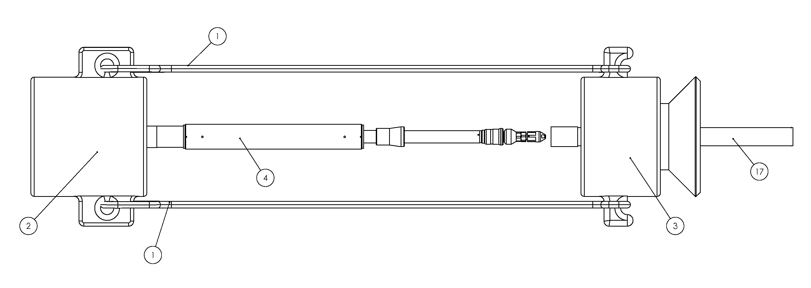
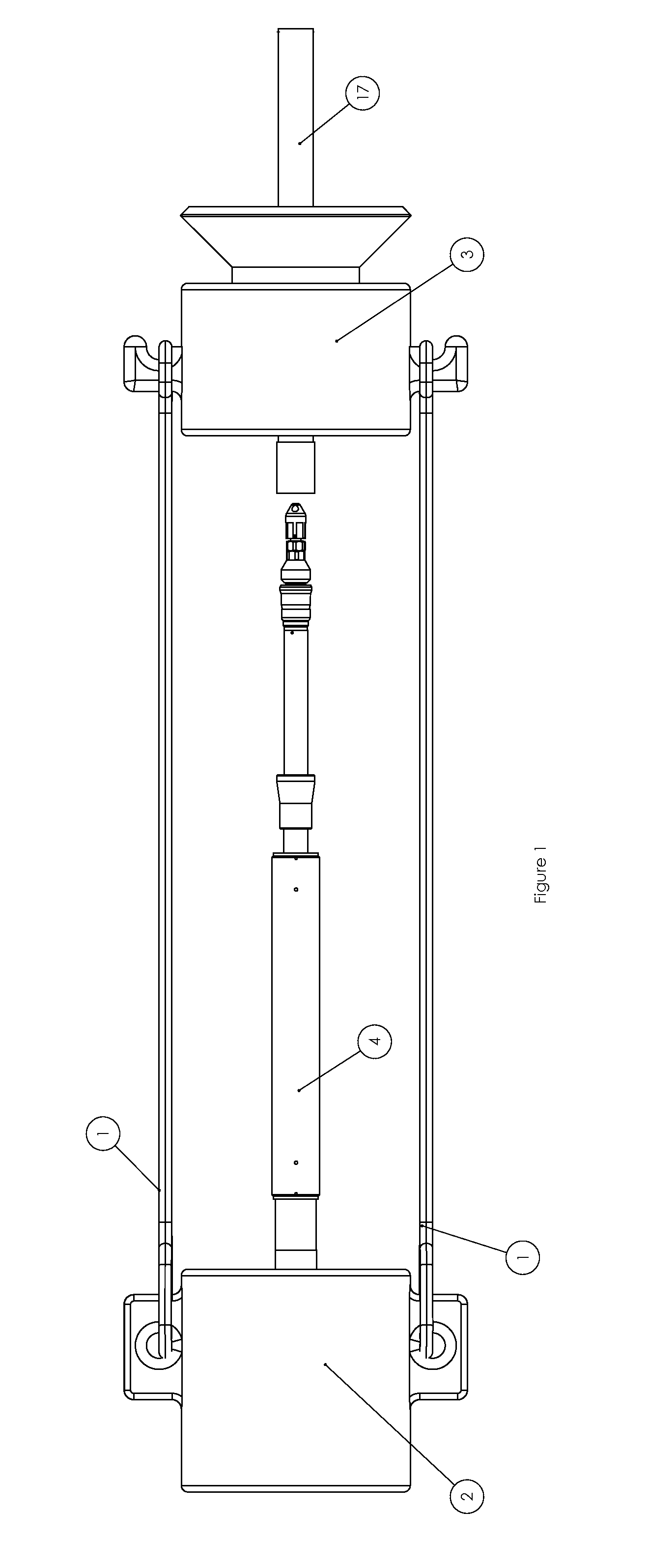
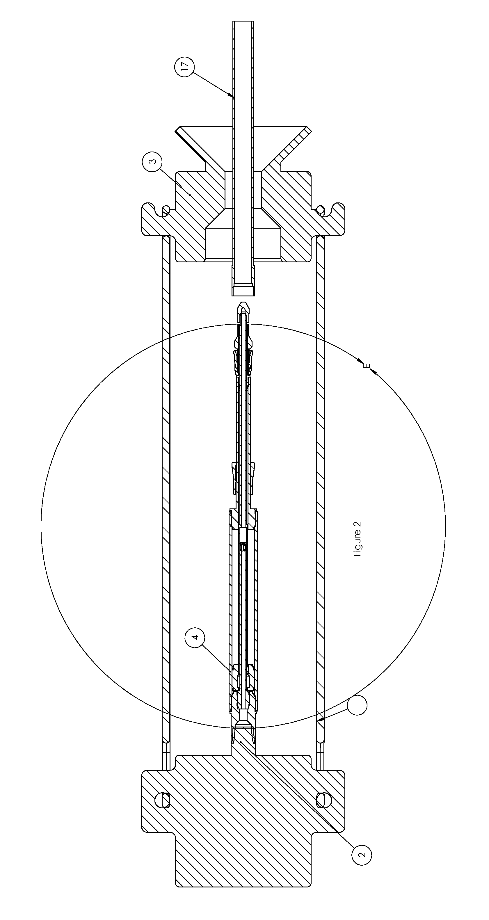
[0020]In FIG. 1 the fill up tool 4 is hanging from the top drive 2. The bails 1 hold up the elevator 3 which is also supported by top drive 2. The elevators are lowered around casing 17. This is also illustrated with FIG. 2 In this position the elevators can swing and move around without interfering with fill up tool 4 since it is positioned above the elevators.

[0021]In FIG. 3 a moveable sealed piston 5 moves inside wall 41 of fill up tool 4. Piston 5 is connected to stroke shaft 51 which is connected to nose 10. There is an upper volume 401 and lower volume 402 that can be manipulated to move piston 5 up or down. FIG. 3A is the valve in the closed position. When piston 5 is in the up position stroke shaft 51 blocks the flow of fluid from inner passage 151 attempting to pass through bore 145.

[0022]In FIG. 4 the fill up tool 4 is extended to fill up the casing 17. Flow through the tool is possible as extension starts and while extension continues to full extension stroke. Alternative...


PUM


Abstract

A fill up tool has an adjustable length to selectively lengthen the fill up a tool or retract to be positioned completely above the elevator so that elevator movement will not interfere with the fill up tool. The seal is fixed to the tool so that the load caused by the pressurized seal does not have to be balanced by the operating force of the piston. A full open valve is operated when the tool is extended to fill up or take flow back.

Description

FIELD OF THE INVENTION[0001]The field of the invention is a circulation and fill up tool where length can be selectively adjusted to lower into the elevator for fill upBACKGROUND OF THE INVENTION[0002]Fill up tools have been use to transfer fluids into and out of the casing or tubulars being run into the well. These tools generally have a seal to allow a pressurized communication to circulate or take flow back. The use of a spring operated check valve allows fluid to be controlled in both directions. Generally these tools will hang between the bails and hang inside or above the elevators. In general practice the seal is inserted into the tubular only when circulating or taking flow back to help reduce wear on the seal.[0003]The standard procedure is to position the fill up tool with spacers so that the seal is positioned just above the top of the casing when being run into the well while the valve or nose of the assembly is hanging down below, inside the elevators. With the use of s...

Claims


Application Information

Patent Timeline
Patent Type & Authority Applications(United States)
IPC IPC(8): E21B21/00E21B21/10E21B17/10E21B33/12
CPCE21B21/00E21B17/1078E21B21/10E21B33/12E21B21/106E21B21/08
Inventor MULLINS, ALBERT AUGUSTUSHICKL, MATTHEW J.MACDONALD, TRAVIS
Owner DRAWWORKS
Learn More