Eureka AIR delivers breakthrough ideas for toughest innovation challenges, trusted by R&D personnel around the world.

Power generation control apparatus for generator and power generation control method of generator

a power generation control and control apparatus technology, applied in the direction of electric generator control, dynamo-electric converter control, control system, etc., can solve the problems of giving a feeling of strangeness, so as to reduce the feeling of strangeness, increase the total number of parts, and increase the effect of total weigh

Inactive Publication Date: 2015-10-01
TOYOTA JIDOSHA KK
View PDF14 Cites 5 Cited by
  • Summary
  • Abstract
  • Description
  • Claims
  • Application Information

AI Technical Summary

Benefits of technology

The power generation control apparatus and method described in this patent provide a way to control the power generation of a generator in a stable and efficient manner. The apparatus includes a device identifier to identify each electrical load device, a storage unit to store the allowable voltage range for each device, an overlap range calculator to determine the overlap voltage range in which the allowable voltage ranges of the devices overlap, and a power generation controller to limit the power generation voltage to this overlap range. This allows for a reduction in output variation and improves the overall performance of the generator. The apparatus and method can be used in vehicles and other applications where stable power generation control is important.

Problems solved by technology

The output variation of the lighting device accompanied with a variation in power generation voltage is likely to be recognized as flicker and is likely to give a feeling of strangeness.
The output variation of the drive device accompanied with a variation in power generation voltage is likely to be recognized as an operation failure or an abnormal operating noise and is likely to give a feeling of strangeness.

Method used


Image

  • Power generation control apparatus for generator and power generation control method of generator
  • Power generation control apparatus for generator and power generation control method of generator
  • Power generation control apparatus for generator and power generation control method of generator

Examples


Embodiment Construction

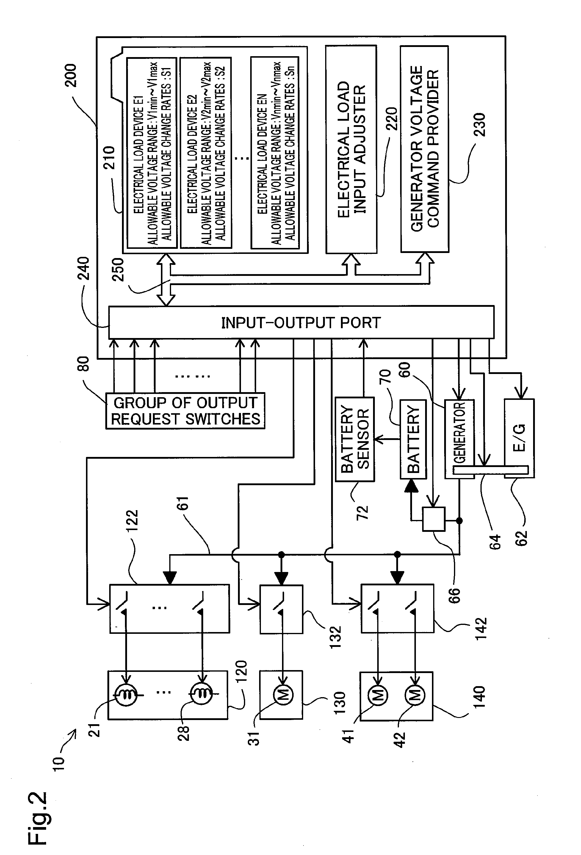
[0020]The following describes embodiments of the invention with reference to the drawings. FIG. 1 is a diagram schematically illustrating a vehicle 10 equipped with various electrical load devices according to one embodiment of the invention. The vehicle 10 has a plurality of lighting devices and a plurality of drive devices as electrical load devices that are output request objects, as described below. The vehicle 10 has headlights 21, front turn signal lamps 22 including width indicators, a instrument illumination light 25, door illumination lamps 24, a vehicle interior light 23, rear turn signal lamps 26, brake lamps 27 and tail lamps 28 including width indicators and a backup light which are located from the vehicle front side, as the plurality of lighting devices. These lights and lamps are subjected to lighting control by a controller 200 (described later), in response to the driver's or vehicle operator's switching operations and device operations. Among these lights and lamp...


PUM


Abstract

A vehicle 10 stores in advance, in a memory 210, an allowable voltage V as a range in which a feeling of strangeness on the basis of an output variation is acceptable, with respect to each of electrical load devices E1 to EN including headlights 21 and a windshield wiper motor 31 mounted on the vehicle 10. The vehicle 10 identifies output requesting electrical devices, which a vehicle operator requires outputs, in response to the vehicle operator's switch operations, reads the allowable voltages V of the identified output requesting electrical load devices from the memory 210, and sets an overlap voltage range in which the read allowable voltages V are overlapped, to a power generation voltage range Vp for power generation control of a generator 60. The vehicle 10 then limits the power generation voltage of the generator 60 to the power generation voltage range Vp and performs power generation control of the generator 60.

Description

TECHNICAL FIELD[0001]The present invention relates to a power generation control apparatus for a generator and a power generation control method of a generator.BACKGROUND ART[0002]The power generation voltage of a generator is supplied to various electrical load devices. For example, the power generation voltage of a generator mounted on a vehicle is supplied to various lighting devices such as headlights of the vehicle, a vehicle interior light and a instrument illumination light for an instrument panel, as well as to various drive devices such as drive motors for a windshield wiper and blowers. The output of each of the electrical load devices including the lighting device and the drive devices is varied with a variation in power generation voltage of the generator as the supplied voltage. More specifically, the lighting device has a variation in light quantity, and the drive device has a variation in driving speed. The output variation of the lighting device accompanied with a va...

Claims


Application Information

Patent Timeline
IPC IPC(8): H02P9/30H02P9/48
CPCH02P9/48H02P9/305
Inventor YOON, TAEJIN
Owner TOYOTA JIDOSHA KK
Why Eureka
Eureka Blog
Learn More