Radioactive gas monitor
- Summary
- Abstract
- Description
- Claims
- Application Information
AI Technical Summary
Benefits of technology
Problems solved by technology
Method used
Image

Examples
embodiment 1
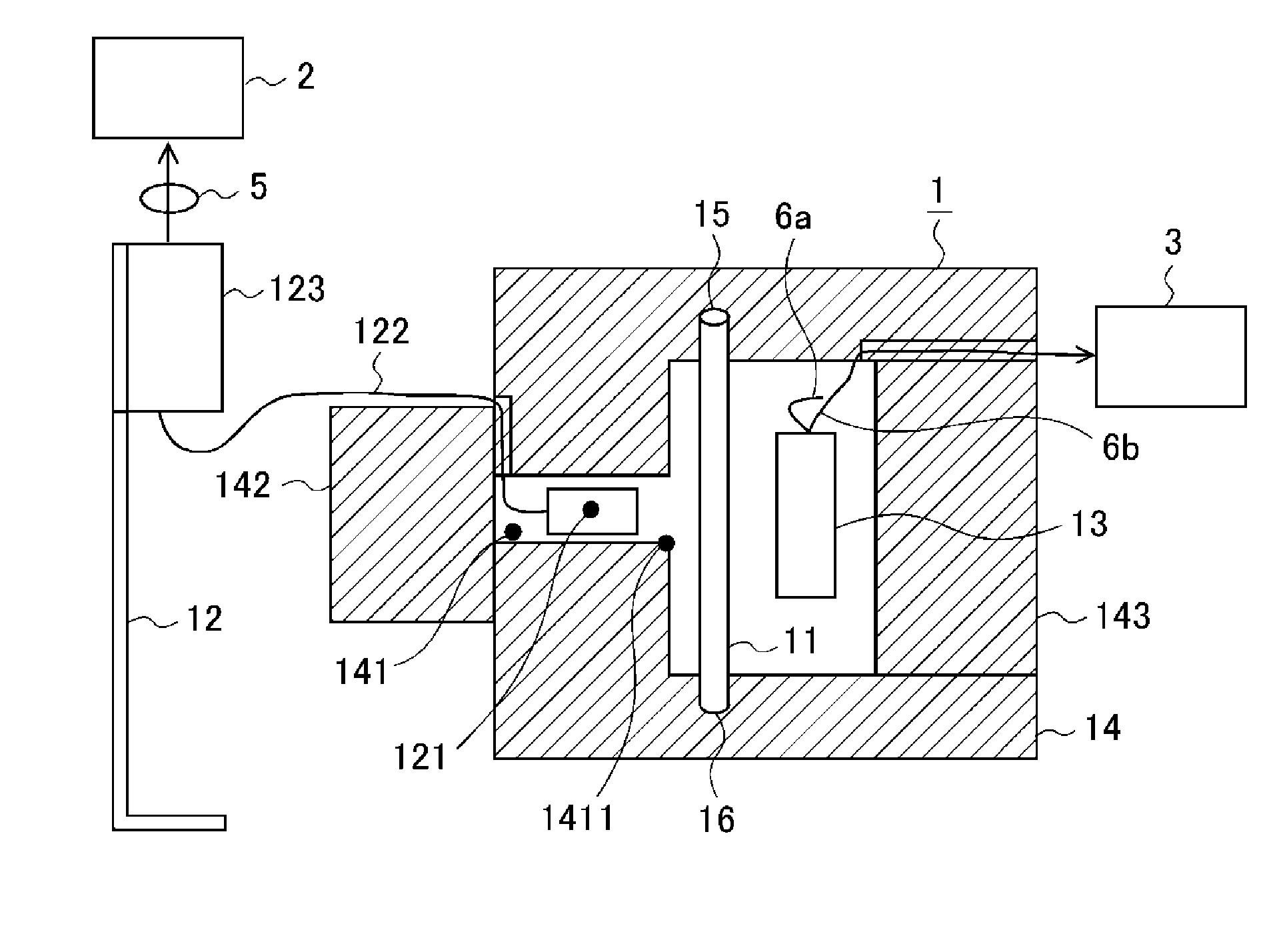
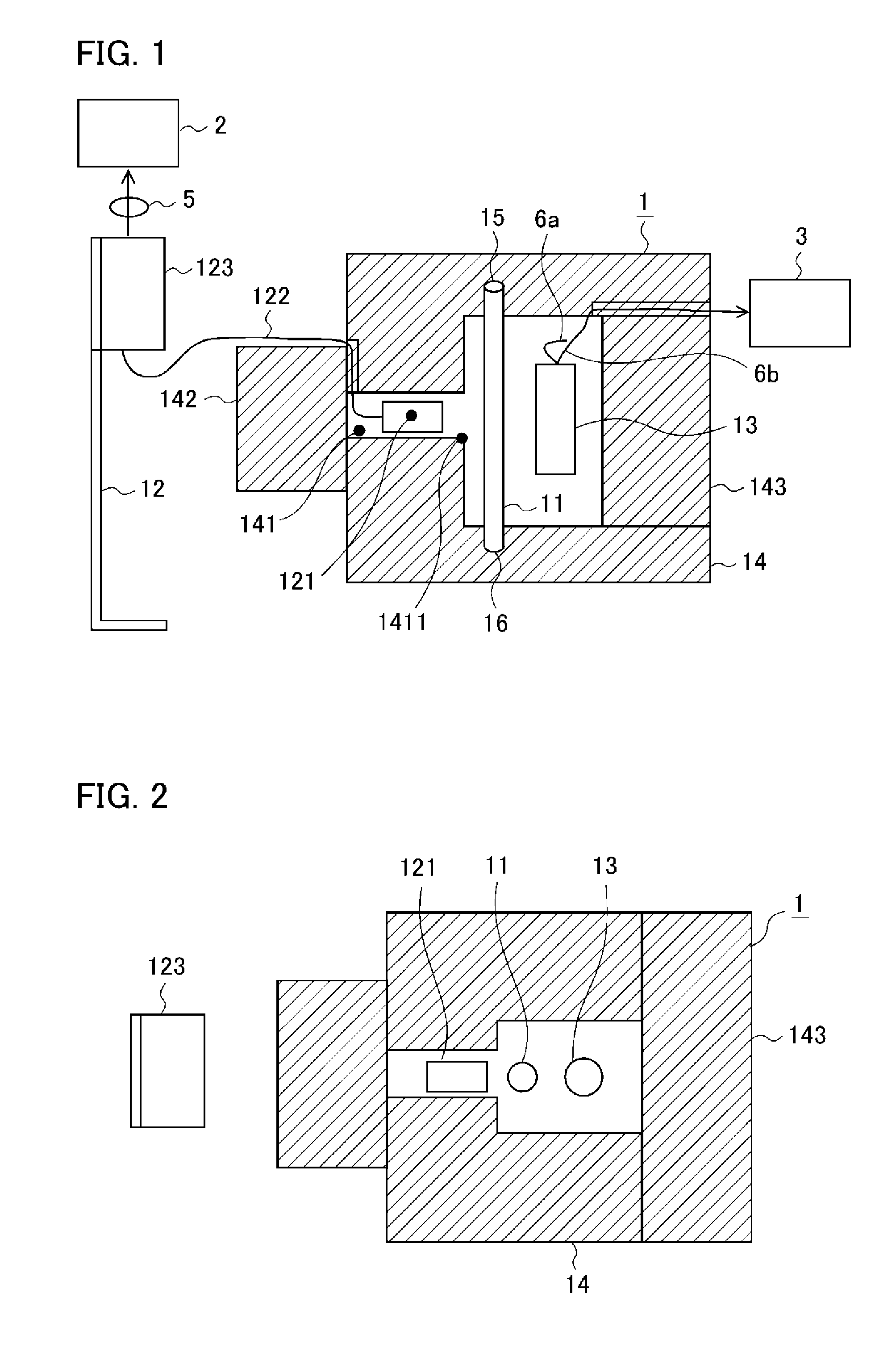
[0033]Hereinafter, a radioactive gas monitor according to Embodiment 1 of the present invention will be described with reference to the drawings. FIGS. 1 and 2 illustrate the radioactive gas monitor according to Embodiment 1. FIG. 1 is a cross-sectional view when laterally viewed, and FIG. 2 is a cross-sectional view when viewed from above. In the drawings, the same reference numerals are given to the same or equivalent elements.
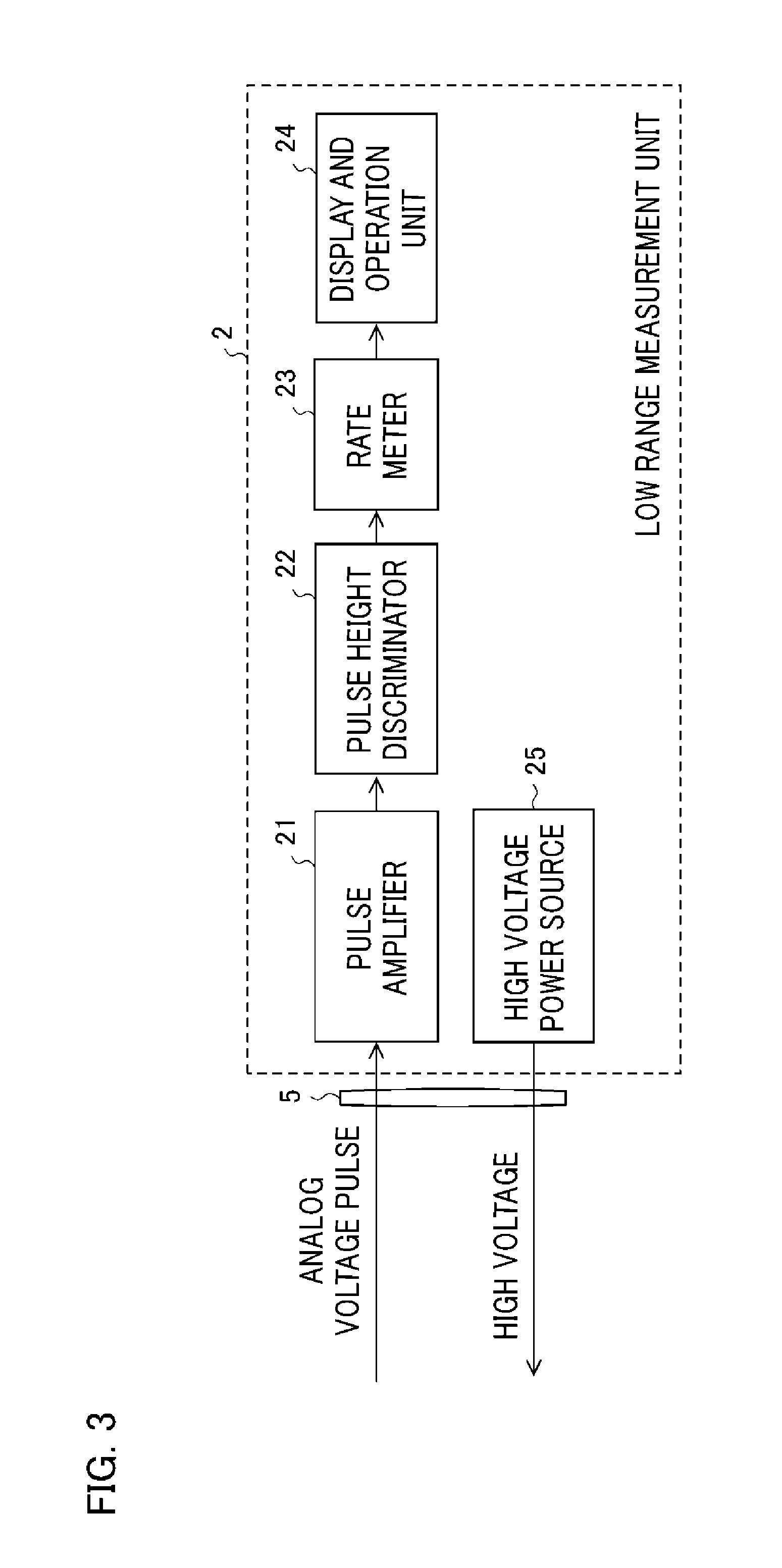
[0034]The radioactive gas monitor according to Embodiment 1 includes, as main configuring elements, a detection unit 1 which detects radiation emitted from radioactive nuclides contained in sample gas, and a measurement unit which processes a signal transmitted from the detection unit 1 and outputs an engineering value corresponding to the radioactive concentration. The measurement unit has a low range measurement unit 2 serving as a first measurement unit and a high range measurement unit 3 serving as a second measurement unit.
[0035]The detection unit 1 inc...
embodiment 2
[0077]FIGS. 7 and 8 illustrate a radioactive gas monitor according to Embodiment 2 of the present invention. FIG. 7 is a cross-sectional view when laterally viewed, and FIG. 8 is a cross-sectional view when viewed from above. In FIG. 7, the same reference numerals are given to the same or equivalent elements in FIG. 1, and description thereof will be omitted.
[0078]In Embodiment 1 described above, the ionization chamber 13 is used as the second detector to which the high concentration side measurement range within all the required measurement ranges is allocated. However, in Embodiment 2, a fibrous scintillation detector 17 is used. A high range measurement unit 4 processes a signal transmitted from the fibrous scintillation detector 17.
[0079]Similar to the columnar scintillation detector 12, the fibrous scintillation detector 17 includes a radiation sensor 171 which emits fluorescence when the radiation is detected, and which outputs a current pulse by converting the fluorescence in...
embodiment 3
[0092]A radioactive gas monitor according to Embodiment 3 of the present invention is configured so that in the radioactive gas monitor similar to that in Embodiment 1 or Embodiment 2 described above, a collimator 146 for narrowing down the radiation incident on the radiation sensors 121 and 171 is disposed inside the detector installing holes 141 and 144 disposed in the shield 14. The other configurations are the same as those in Embodiment 1 or Embodiment 2 described above. Therefore, the different configuration will be described using FIG. 1.
[0093]For example, when the measurement range of the columnar scintillation detector 12 is suitably arranged, if only a distance of the head of the radiation sensor 121, the window 1411, and the detection tube 11 is adjusted, a wide space is required inside the shield 14.
[0094]Therefore, in Embodiment 3, as illustrated in FIG. 11, the collimator 146 is disposed near the window 1411 through which the detection tube 11 of the detector installin...
PUM
 Abstract
Description
Claims
Application Information
 - R&D
- Intellectual Property
- Life Sciences
- Materials
- Tech Scout
- Unparalleled Data Quality
- Higher Quality Content
- 60% Fewer Hallucinations
Browse by: Latest US Patents, China's latest patents, Technical Efficacy Thesaurus, Application Domain, Technology Topic, Popular Technical Reports.
© 2025 PatSnap. All rights reserved.Legal|Privacy policy|Modern Slavery Act Transparency Statement|Sitemap|About US| Contact US: help@patsnap.com