Liquid transport device
a technology of liquid transport device and electrode, which is applied in the direction of temperature-sensitive devices, positive displacement liquid engines, machines/engines, etc., can solve the problems of no disclosure and complex wiring of electrodes
- Summary
- Abstract
- Description
- Claims
- Application Information
AI Technical Summary
Benefits of technology
Problems solved by technology
Method used
Image


Examples
first embodiment
[0082]FIGS. 1 to 3B illustrate a liquid transport device according to a first embodiment.
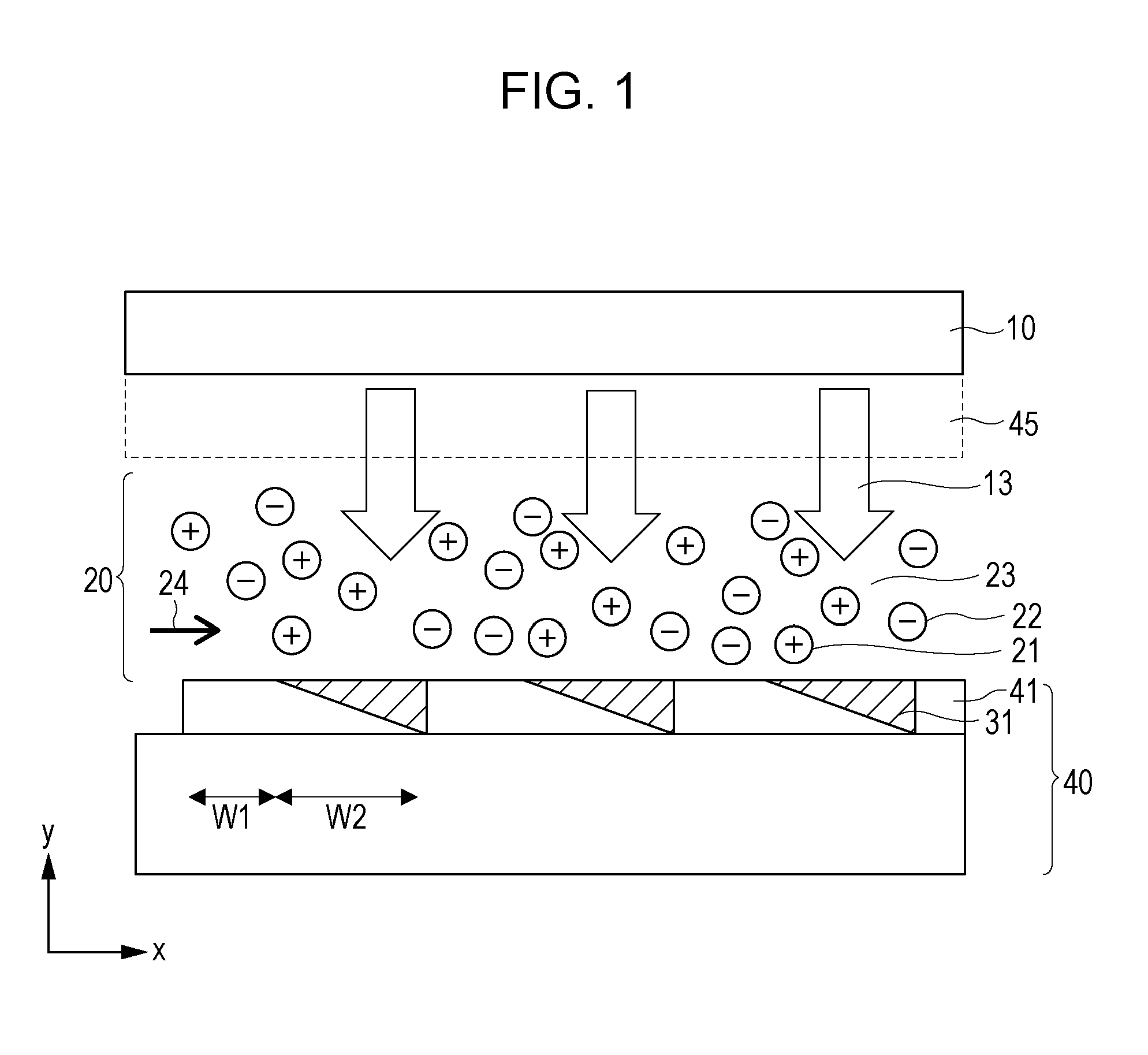
[0083]Referring to FIG. 1, the substrate 40, the light radiation unit 10, and the channel 20 are provided. The light radiation unit 10 radiates light toward the substrate 40. The substrate 40 and the light radiation unit 10 face each other. The channel 20 is disposed between the substrate 40 and the light radiation unit 10 and allows the liquid 23 containing ions indicated as the positive ions 21 and the negative ions 22 to be transported therethrough.
[0084]Reference numeral 45 denotes the transparent substrate. The transparent substrate 45 and the light radiation unit 10 face the substrate 40, so that the surface 41 of the substrate 40 is irradiated with the light 13 emitted from the light radiation unit 10.
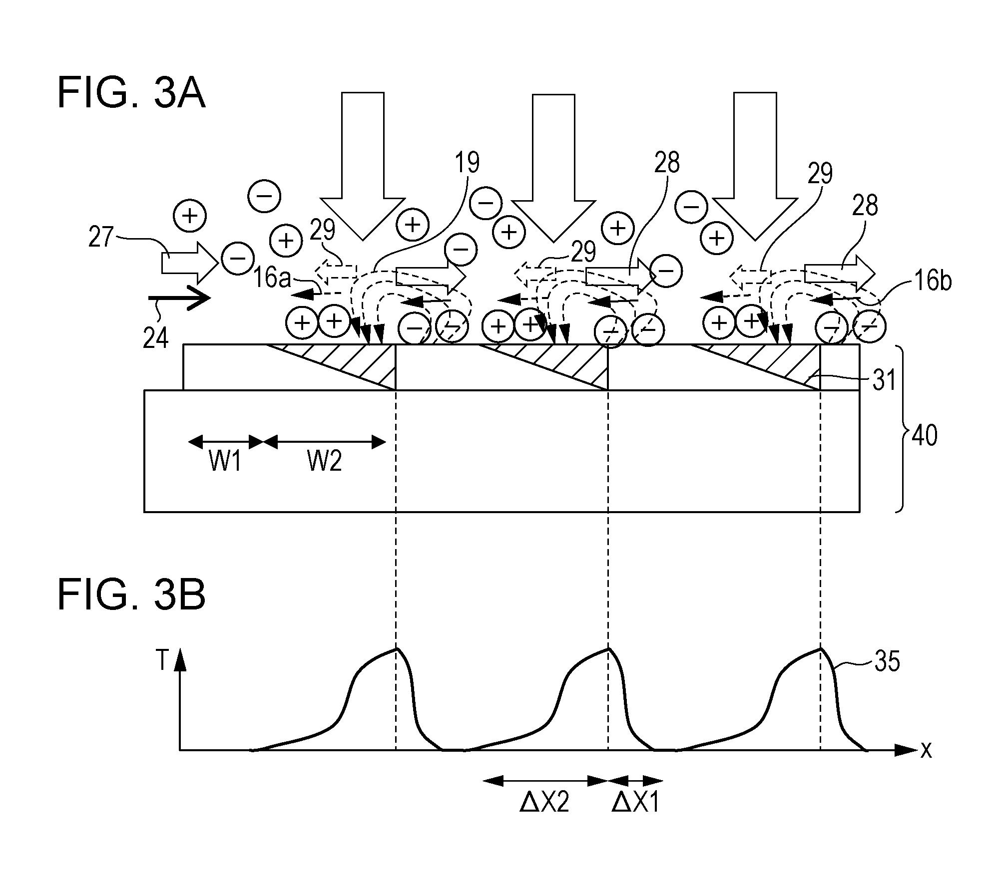
[0085]The surface 41 of the substrate 40 includes the surface portions 31 in each of which the asymmetrical temperature distribution is produced in the direction 24 in which the liquid 23 is...
second embodiment
[0130]A liquid transport device of a second embodiment will be described with reference to FIGS. 5A and 5B.
[0131]Although a device of the present embodiment is structured similarly to the device of the first embodiment, there are main differences between these devices as follows: that is, in the device of the present embodiment, the substrate 40 used for the device of the present embodiment includes a surface that has irregularities 46 in a direction substantially perpendicular to the direction 24 in which the liquid is to be supplied, and a heat holding layer 11 that holds heat generated by the light radiation 13 is provided below the surface of the substrate 40. A cooling layer 12 is disposed below the heat holding layer 11.
[0132]By setting surfaces 31 where the asymmetrical temperature distributions are produced in recess portions of the irregularities 46, the flows derived from the slip velocity 29 (Vs2) generated in a direction opposite to the direction 24 in which the liquid i...
third embodiment
[0138]A liquid transport device of a third embodiment will be described with reference to FIGS. 6A and 6B.
[0139]Although a device of the present embodiment is structured similarly to the device of the first embodiment, there are main differences between these devices as follows: that is, in the device of the present embodiment, the surfaces 31b where the optical absorption coefficient distribution varies stepwise in the direction 24 in which the liquid is to be supplied are periodically provided, and the heat holding layer 11 and so forth illustrated in FIG. 5A are provided.
[0140]In the device of the present embodiment, the surfaces 31b where the asymmetrical optical absorption distributions vary stepwise are adopted so as to form the asymmetrical temperature distributions 35b. This can simplify the formation of the optical absorption layer.
[0141]The device illustrated in FIGS. 6A and 6B uses two optical absorption coefficients of white and black, and the area of black regions that ...
PUM
 Abstract
Description
Claims
Application Information
 - R&D
- Intellectual Property
- Life Sciences
- Materials
- Tech Scout
- Unparalleled Data Quality
- Higher Quality Content
- 60% Fewer Hallucinations
Browse by: Latest US Patents, China's latest patents, Technical Efficacy Thesaurus, Application Domain, Technology Topic, Popular Technical Reports.
© 2025 PatSnap. All rights reserved.Legal|Privacy policy|Modern Slavery Act Transparency Statement|Sitemap|About US| Contact US: help@patsnap.com