Eureka AIR delivers breakthrough ideas for toughest innovation challenges, trusted by R&D personnel around the world.

Desalter operation

a technology of desalters and desalters, which is applied in the field of desalter operation, can solve the problems of reducing workable volume of rag layers, shortening the electric circuit, and especially problematic formation of rag layers, so as to improve the separation of oil and water phases, promote dehydration of emulsions, and enhance dehydration of oil/water emulsions

Active Publication Date: 2015-09-24
EXXON RES & ENG CO
View PDF6 Cites 7 Cited by
  • Summary
  • Abstract
  • Description
  • Claims
  • Application Information

AI Technical Summary

Benefits of technology

The patent text describes the use of a chemical called sodium carbonate to improve the separation of oil and water phases in a desalting process. This method also promotes the dehydration of the oil / water emulsion and reduces the stability of the oil / bulk-resolved-water interface, resulting in improved efficiency of the process compared to using a demulsifier before the desalter vessel.

Problems solved by technology

Rag layer formation is especially problematic for crude with high amount of natural surfactants and / or solids.
The growth of rag layer reduces workable volume and may short the electric circuit and force unplanned and costly desalter shut down.
Additionally, processing crudes with high rag layer formation tendencies in rent desalter configurations may cause poor desalting (salt removal) efficiency due to solids build up at the bottom of the vessel, and / or a solids-stabilized rag layer leading to erratic level control and insufficient residence time for proper water / oil separation.
Formation of the rag layer has become a major desalter operating concern, generating desalter upsets, increased preheat train fouling, and deteriorating quality of the brine effluent and disruption of the operation of the downstream wastewater treatment facilities.
Intractable emulsions of this kind comprising oil, water and solids make adequate separation and oil recovery difficult.
This results in expensive treating or handling procedures or pollution problems as well as the fact that crude oil is also lost with these emulsions and slop streams.
Refinery sites which process high solids-content crudes have the most pervasive problems with emulsion formation, Heavy crude oils and bitumens from Western Canada which contain elevated levels of small clay fines and other small solids are particularly prone to forming large volumes of highly stable emulsion and with such feeds, growth of the rag layer is more prevalent.
These feeds are, however, being introduced to refineries in greater quantities despite two main disadvantages related to the efficacy of desalting.
First, the viscosity of these crudes can be quite high, so transport of water through the feed is slower than in high API gravity crude.
The use of the demulsifier has proven to be effective in reducing emulsion stability between electrodes in a desalter, but may not be effective in reducing the rag layer build-up which is mainly due to stability of the oil / bulk-resolved-water interface.

Method used


Image

  • Desalter operation
  • Desalter operation
  • Desalter operation

Examples


example 1

[0031]Rest Time Measurement of Crude without Sodium Carbonate

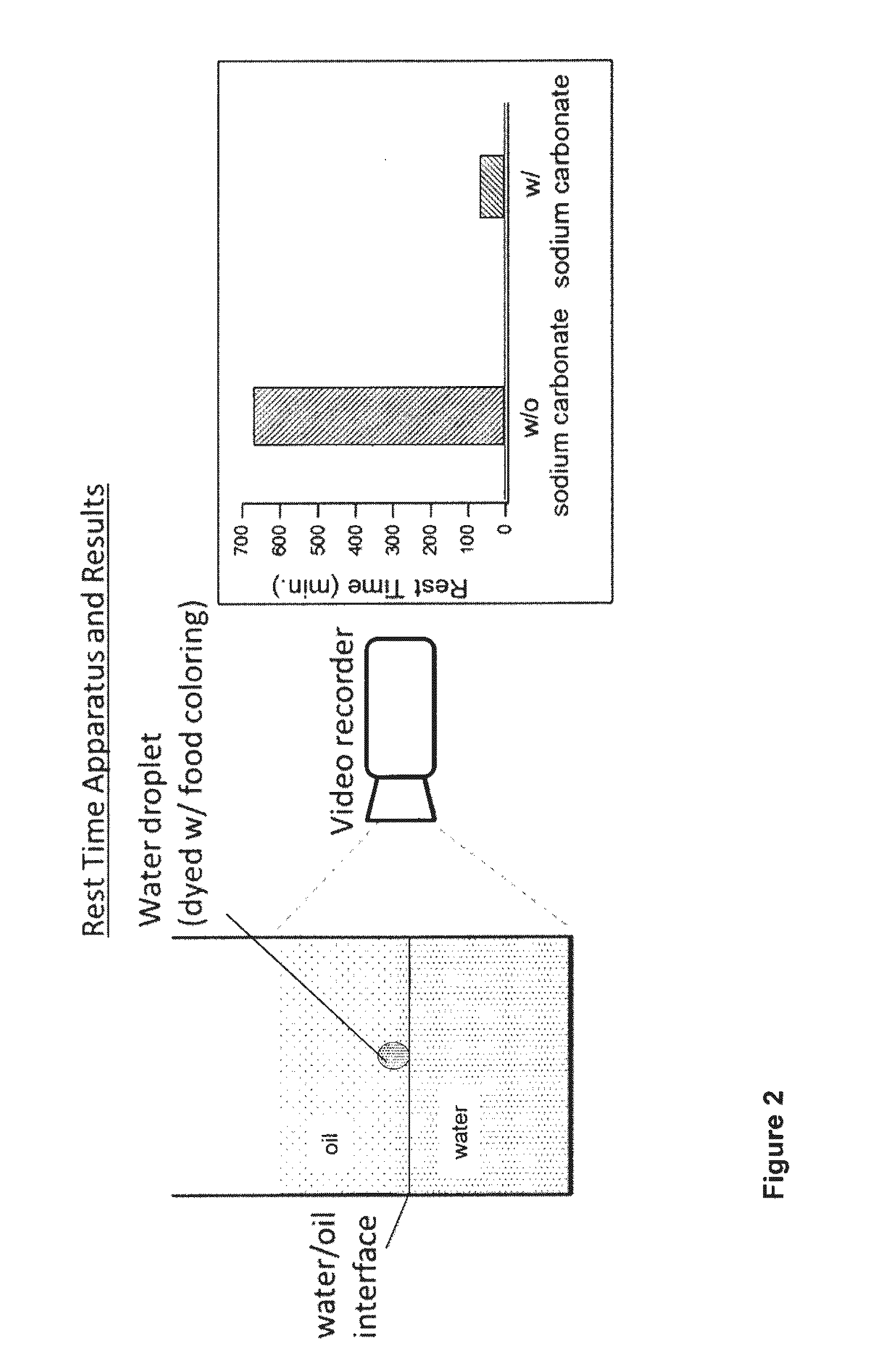
[0032]The Rest Time method was used to measure the stability of the water / oil interface and its effect on preventing water droplets to immerse into the bottom water phase. In this measurement 85 mL of crude is left on 220 mL deionized water in a cylindrical glass container with internal diameter of 7.7 cm. After 30 minutes several droplets of water, which was dyed with food coloring, are dropped on the oil surface. When the droplets reach the interface between water and oil they rest at that interface before immersing into the water phase. The “Rest Time” is the time measured with the aid of a video camera, a water droplet rests at the water / oil interface before entering and immersing into the water phase.

[0033]The average rest time when no sodium carbonate was used in effluent water was measured to be 671 minutes; the simplified Rest Time experimental setup and results are shown in FIG. 2.

example 2

[0034]Rest Time Measurement of Crude with Sodium Carbonate in Water

[0035]The Rest Time value when 0.1% sodium carbonate was added to the water phase below the oil phase was measured at 66 minutes. Examples 1 and 2 therefore demonstrate that when sodium carbonate was added to the water phase the oil / water interface was weakened and the water droplets were able to penetrate through the water / oil interface at much shorter time.

example 3

[0036]Electrostatic Dehydration and Precipitation in the Absence of Sodium Carbonate

[0037]Aliqots of water and crude oil were heated to 85° C. Preheated water (4 mL)

[0038]was added to 90 mL. of preheated crude oil and blended for 10 seconds at half full power using a Waring™ blender to generate a water-in-oil emulsion. The emulsion (74.2 mL) of was then poured in a transparent vessel of an Electrostatic Dehydration and Precipitation Tester (EDPT) (from Inter AV inc.) which was preheated to 90° C. and contained 0.8 mL water. The vessel's cap was tightened and temperature was then increased to 120° C.

[0039]Voltages of 500, 1500 and 3000 volts for duration of one minute were applied respectively at 10, 21, 32 minutes after the EDPT reached 120° C. A voltage of 3000 volts for duration of one minute was applied at 43, 54, 65, 75, 105 and 120 minutes after the EDPT reached 120° C. The amount of the effluent water at the bottom of the vessel was measured at 5, 16, 27, 38, 49, 60, 71, 101, ...


PUM

PropertyMeasurementUnit
vertical distanceaaaaaaaaaa
particle sizesaaaaaaaaaa

Abstract

A petroleum desalting process is improved by introducing the an alkaline compound such as sodium carbonate into the water phase, preferably in the vicinity of the water / oil interface which forms between the oil and water layers. This makes the rapid and effective separation of the oil and water phases from the emulsion layer possible.

Description

CROSS REFERENCE TO RELATED APPLICATIONS[0001]This application is a continuation-in-part of application Ser. No. 14 / 556,398, filed 1 Dec. 2014 which claimed priority from application Ser. No. 61 / 918,843, filed 20 Dec. 2013. The present application claims the benefit under 35 USC 120 of application Ser. No. 14 / 556,398.FIELD OF THE INVENTION[0002]This invention relates to the operation of petroleum desalters and in particular to an improved method of adding demulsifiers to the desalting process.BACKGROUND OF THE INVENTION[0003]Crude petroleum normally contains salts that may corrode refinery units; salt is removed from the crude oil by a process known as “desalting”, in which hot crude oil is mixed with water and a suitable demulsifying agent to form a water-in-oil emulsion which provides intimate contact between the oil and water, transferring salt into the water. The salty emulsion is then passed into a high voltage electric field inside a closed separator vessel. The electric field ...

Claims


Application Information

Patent Timeline
Patent Type & Authority Applications(United States)
IPC IPC(8): C10G33/02C10G21/08C10G1/00
CPCC10G33/02C10G21/08C10G1/002B01D17/047B01D17/06C10G19/02C10G31/08C10G32/02C10G33/04C02F1/463
Inventor YEGANEH, MOHSEN SHAHMIRZADILUCCHESI, ROBERT P.HEGNER, JESSICA LYNNFLYNN, RICHARD W.
Owner EXXON RES & ENG CO
Why Eureka
Eureka Blog
Learn More