Motion picture camera arrangement and method of operating a motion picture camera arrangement

Active Publication Date: 2015-09-03
ARNOLD & RICHTER CINE TECHN & BETRIEBS
View PDF5 Cites 35 Cited by
  • Summary
  • Abstract
  • Description
  • Claims
  • Application Information

AI Technical Summary

Benefits of technology

The present invention aims to provide an improved method for operating a motion picture camera arrangement that allows for a smooth display of the taken images with minimal latency at the display device. The invention achieves this by constantly phasing the image capture and display, reducing image flickering and ensuring that the display device operates at a desired display rate. The constant phasing also eliminates the need for a long latency time between image capture and display, allowing for a more efficient and effective display of image information. The invention also includes a method for fixing the display rate, ensuring a smooth display without operation outside of the permissible range. Additionally, the invention reduces latency time by simultaneously reading and writing images to the buffer memory, minimizing the delay between the sensor exposure and display. This approach optimizes the tracking of image content and simplifies the carrying out of pan shots for the user.

Problems solved by technology

A display of the images taken by an electronic motion picture camera at a viewfinder or monitor at the same display rate, i.e. likewise 24 fps, can result in perceptible image flicker.
The resulting different display durations of the individual frames, i.e. the different display durations perceived by a viewer of the display device, can result in a jerky and less smooth perception.
In addition, due to a constantly varying phasing between the image capture and the image display, an undesirably high delay can result between the taking of an image and the display of this image at the display device (so-called latency time).

Method used


Image

  • Motion picture camera arrangement and method of operating a motion picture camera arrangement
  • Motion picture camera arrangement and method of operating a motion picture camera arrangement
  • Motion picture camera arrangement and method of operating a motion picture camera arrangement

Examples


Embodiment Construction

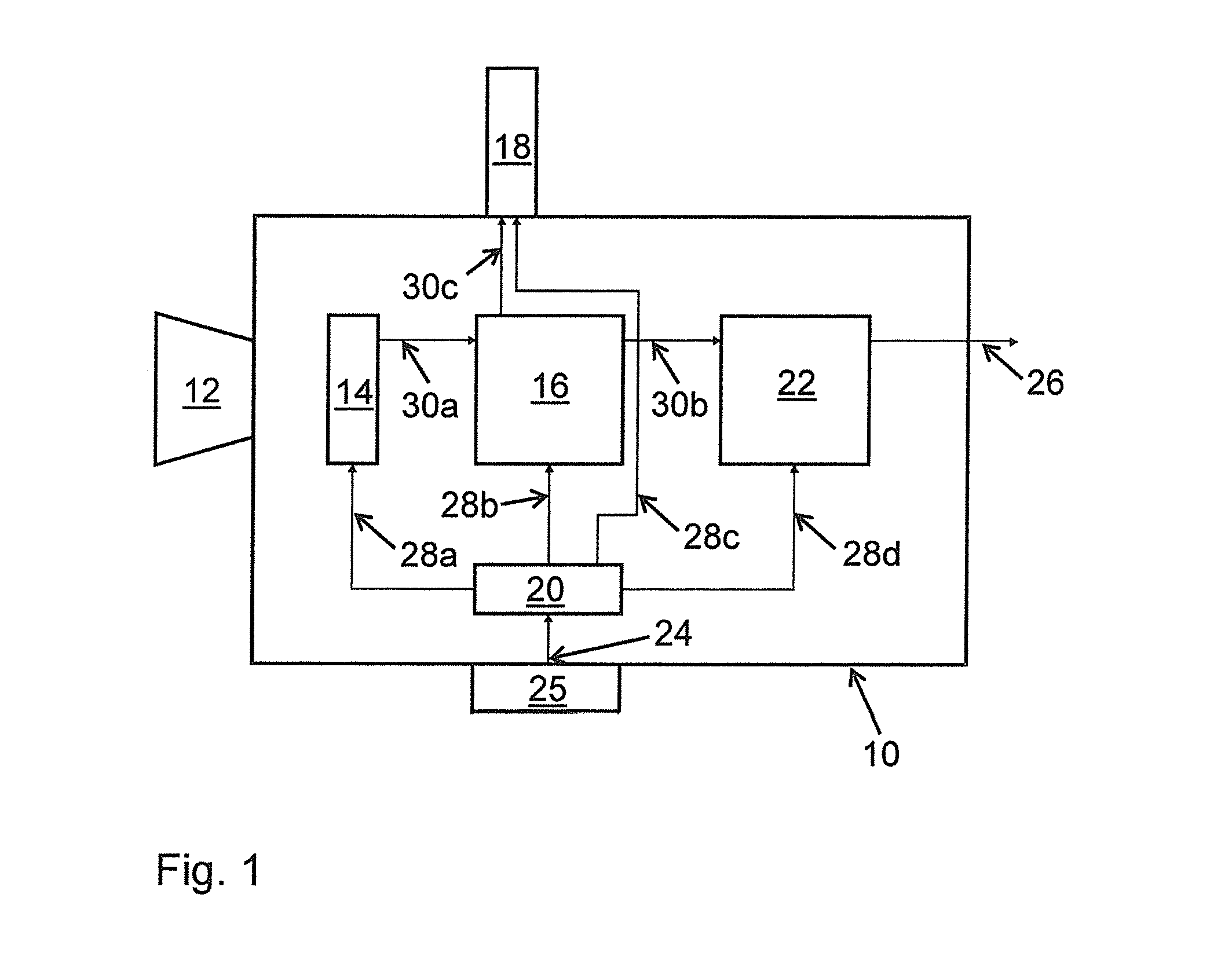
[0047]FIG. 1 schematically shows a motion picture camera arrangement having a motion picture camera 10 at which a display device 18, for example an electronic viewfinder, is provided. Alternatively or additionally to an electronic viewfinder, the display device 18 can have an external monitor which does not have to be fixedly connected to the motion picture camera 10. The display device 18 (electronic viewfinder or external monitor) can display the received image data at a display rate which is fully variably settable within a predefined permitted range. For this purpose, the display device 18 can, for example have an LCD (liquid crystal display), an LCOS (liquid crystal on silicon) display or an OLED (organic light-emitting diode) display.

[0048]The motion picture camera 10 comprises an objective 12 which images the images to be taken onto an image sensor 14. The image sensor 14 can be operated at a fully variable frame rate selectable by the user to capture motion picture sequences...


PUM


Abstract

A motion picture camera arrangement comprises a motion picture camera and a display device, wherein the motion picture camera has an image sensor for taking images at a variable frame rate and wherein the display device displays the taken images at a settable display rate. A method of operating the motion picture camera arrangement comprises the steps of: selecting a frame rate; determining a setting value for the display rate of the display device, wherein the setting value corresponds, in dependence on the selected frame rate, either to the selected frame rate or to a product or quotient of the selected frame rate and a whole-number multiplier or divisor; operating the image sensor at the selected frame rate; and operating the display device using the determined setting value for the display rate.

Description

CROSS-REFERENCE TO RELATED APPLICATIONS[0001]This application claims priority of German Patent Application 102014102689.6 filed on Feb. 28, 2014.FIELD OF THE INVENTION[0002]The present invention relates to a method of operating a motion picture camera arrangement which comprises a motion picture camera and a display device, wherein the motion picture camera has an image sensor for taking images using a selectable, continuously or quasi-continuously variable frame rate, and wherein the display device displays, i.e. shows visually, the taken images at a display rate which can be set at least within a permitted range. The invention further relates to a corresponding motion picture camera arrangement.BACKGROUND OF THE INVENTION[0003]Such electronic motion picture cameras (also referred to as video cameras) can generate and record digital motion picture sequences and / or can transfer them to an external recording apparatus. To set and monitor the image section and / or camera parameters suc...

Claims


Application Information

Patent Timeline
IPC IPC(8): H04N5/222G09G5/00H04N5/14H04N7/01H04N5/225H04N5/232
CPCH04N5/2228H04N5/2251H04N5/23293G09G2360/02H04N7/013G09G5/005G09G2310/02H04N5/147H04N5/783H04N5/772H04N1/00129H04N23/63H04N7/0132
Inventor JACUMET, KLAUS
Owner ARNOLD & RICHTER CINE TECHN & BETRIEBS
Why Eureka
Try Eureka