
Planar antenna microwave module

a microwave module and planar antenna technology, applied in the field of wireless sensors, can solve the problems of large design size, long production cycle, high cost, etc., and achieve the effects of short production cycle, small design size, and simple manufacturing process

Inactive Publication Date: 2015-08-20
HYTRONIK ELECTRONICS CO LTD
View PDF6 Cites 6 Cited by
  • Summary
  • Abstract
  • Description
  • Claims
  • Application Information

AI Technical Summary

Benefits of technology

The present invention provides a planar antenna microwave module with a simplified structure, small design size, simple process, short production cycle, and low costs. The antenna boards have independent and separate structures with high economic benefits. In summary, this invention allows for a more efficient and cost-effective solution for microwave modules.

Problems solved by technology

A conventional 5.8 GHZ planar antenna microwave module is manufactured by using a process of laminating four layers of high frequency boards and drilling blind vias, and therefore has a relatively large design size, a complicated manufacturing process, a long production cycle, high costs, and a low price / performance ratio, and is not suitable for large-scale applications.

Method used


Image

  • Planar antenna microwave module
  • Planar antenna microwave module
  • Planar antenna microwave module

Examples


Embodiment Construction

[0026]The present invention is further described below in detail with reference to the embodiments and accompanying drawings.

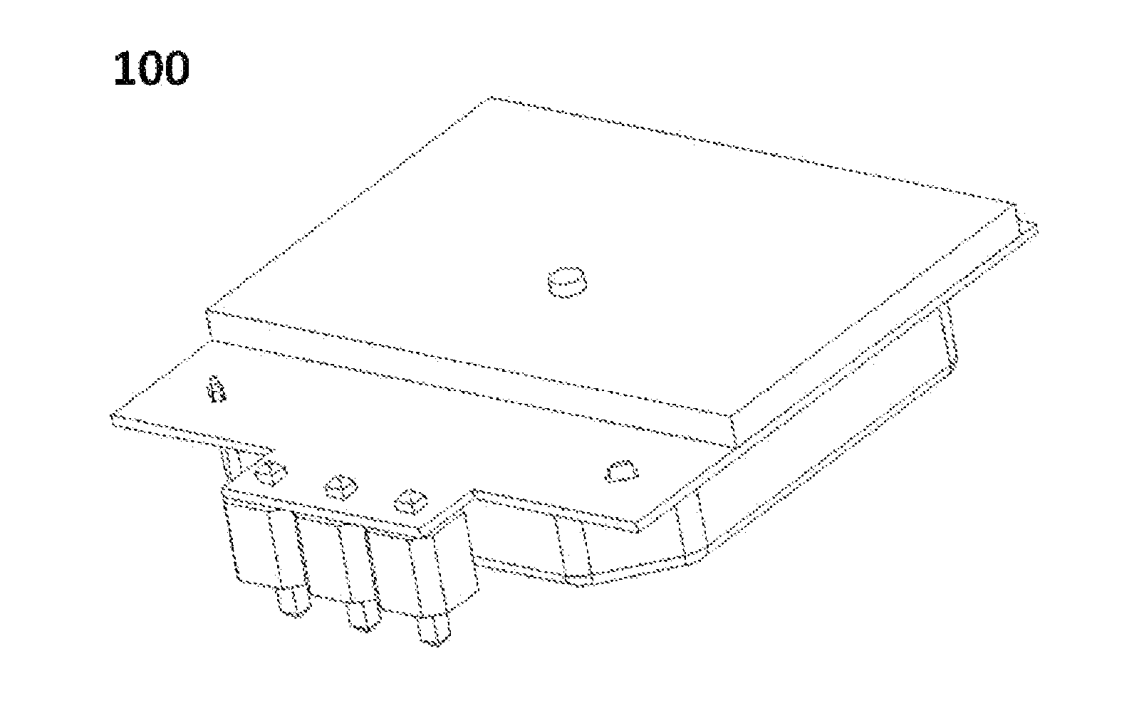
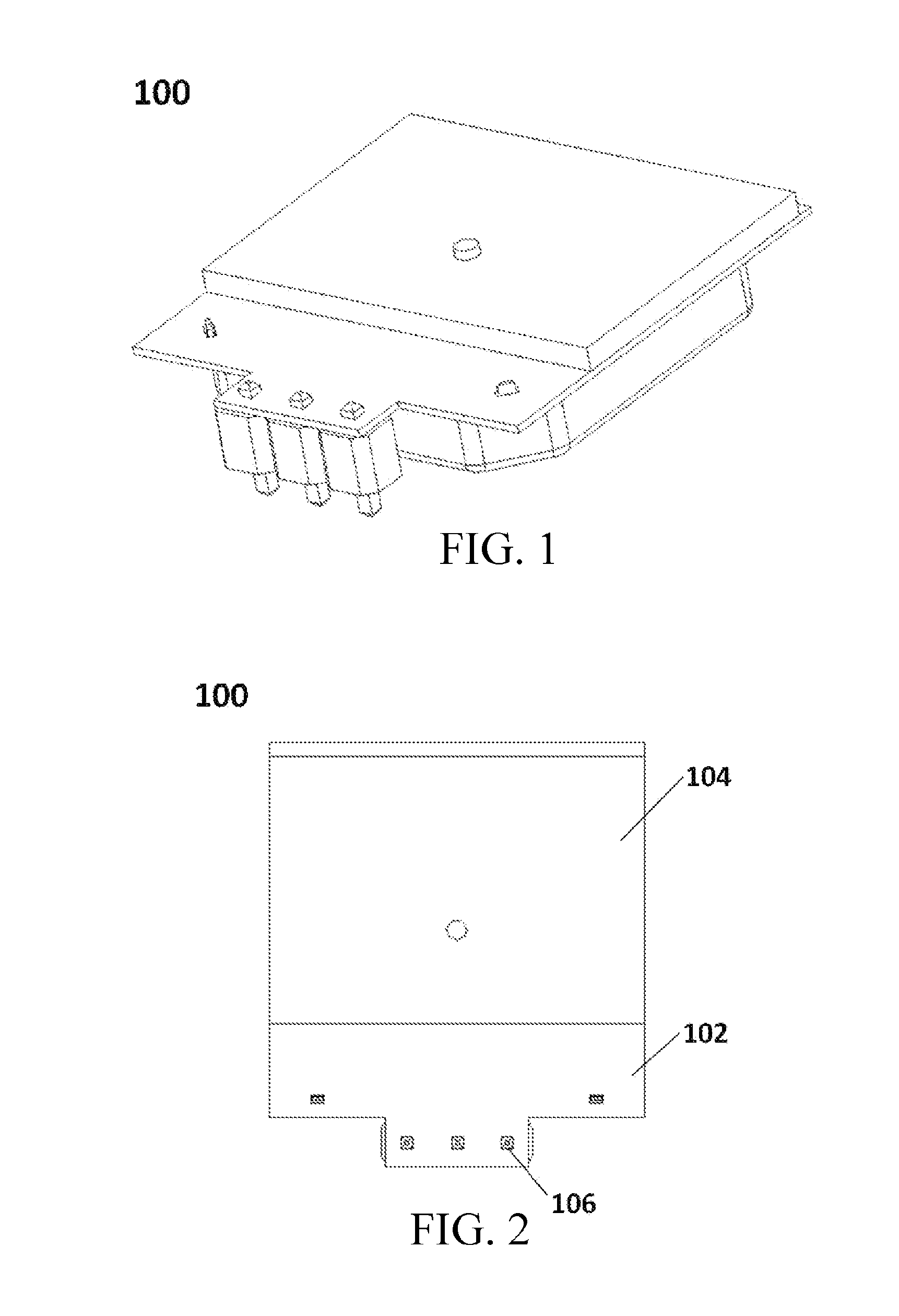
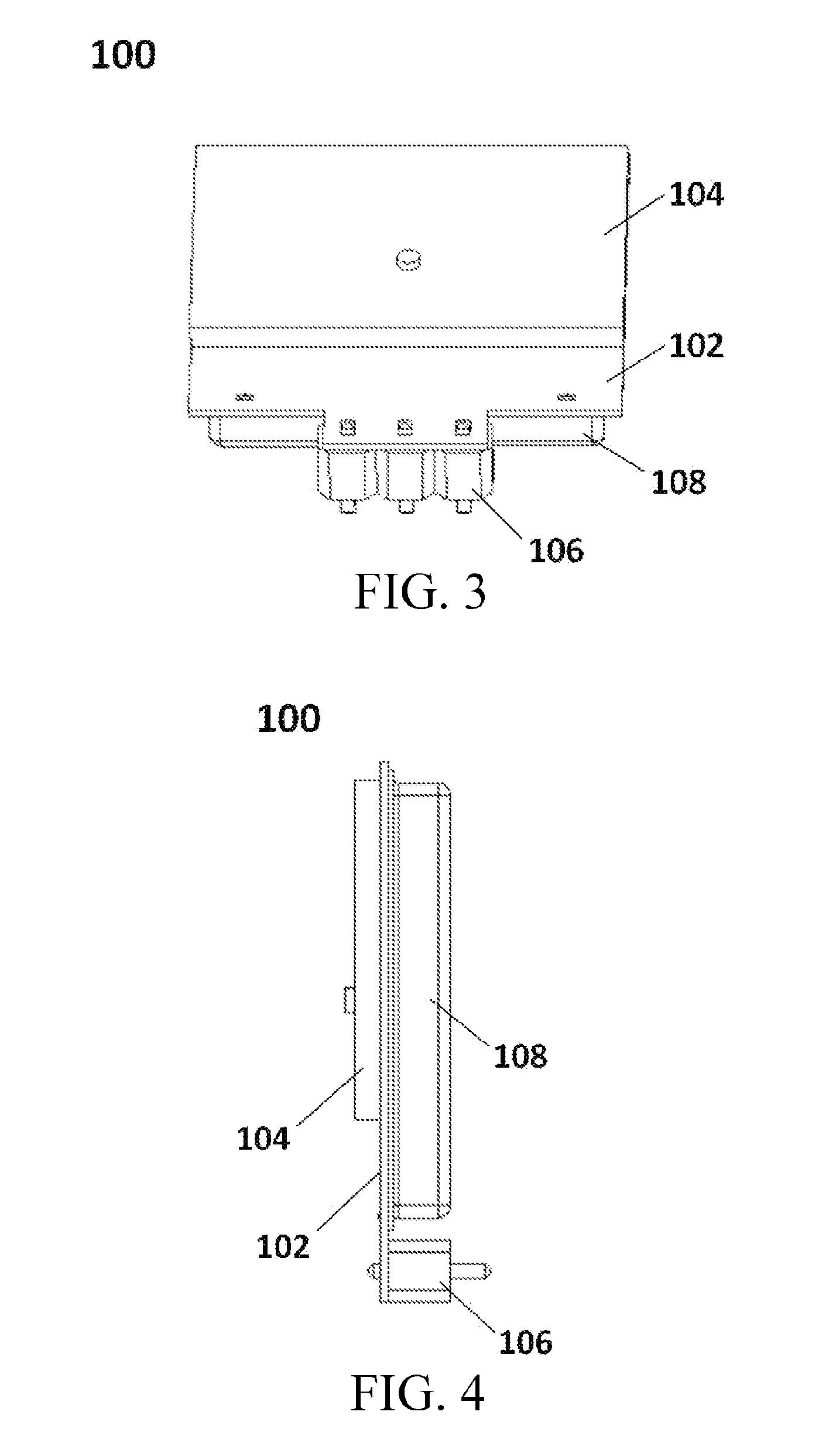
[0027]As shown in FIG. 1 to FIG. 9, a 5.8 GHz planar antenna type microwave sensor 100 includes: an oscillation circuit board 102, an antenna board 104, a pin header component 106, and a metal shielding can 108. The oscillation circuit board 102 includes an upper surface and a bottom surface. The antenna board 104 is fixedly disposed on the bottom surface of the oscillation circuit board 102. One side of the oscillation circuit board 102 is provided with an assembly portion, the pin header component 106 is jointed with the assembly portion of the oscillation circuit board 102, and the metal shielding can 108 covers the upper surface of the oscillation circuit board 102.

[0028]The oscillation circuit board includes a board body of the oscillation circuit board, a microwave oscillator, a microwave Schottky diode double balanced mixer, and an IF doppler signal out...


PUM


Abstract

The present invention discloses a planar antenna microwave module, including an oscillation circuit board and a planar antenna board. The oscillation circuit board is a double-sided printed circuit board. The planar antenna board is a double-sided PCB independent of the oscillation circuit board. PCB copper foil of the planar antenna board forms a transmitting / receiving planar antenna. The planar antenna is laminated on a bottom surface of the oscillation circuit board by using a solder joint that runs through and electrically connects two layers of PCB copper foil, and is electrically connected to the oscillation circuit board through the solder joint. The antenna boards in the present invention are of independent and separate structures, and have a small design size, a simple manufacturing process, a short production cycle, low costs, and high economic benefits.

Description

CROSS REFERENCE TO RELATED APPLICATIONS[0001]The present application is a Continuation-in-part Application of PCT application No. PCT / CN2013 / 075808 filed on May 17, 2013, which claims the benefit of Chinese Patent Application No. 201320198998.1 filed on Apr. 19, 2013. All the above are hereby incorporated by reference.BACKGROUND[0002]1. Technical Field[0003]The present invention relates to the field of wireless sensors, and in particular, to a planar antenna microwave module.[0004]2. Related Art[0005]A basic principle of a 5.8 GHZ planar antenna microwave module is the theory of Doppler effect: electromagnetic wave field strength with a frequency of 5.8 GHZ is generated; the frequency and amplitude of a reflected echo change when a moving target object is detected; and then a valid electrical signal is output after circuit detection processing. A conventional 5.8 GHZ planar antenna microwave module is manufactured by using a process of laminating four layers of high frequency boards...

Claims


Application Information

Patent Timeline
IPC IPC(8): H01Q1/24G01S13/50
CPCH01Q23/00G01S7/032G01S13/56H01Q1/2283H01Q9/0407H01Q1/247Y02B20/40G01S13/505
Inventor CHENG, YABING
Owner HYTRONIK ELECTRONICS CO LTD
Learn More