
Thermal Management Systems for Energy Storage Cells Having High Charge/Discharge Currents and Methods of Making and Using Thereof

a technology of energy storage cells and management systems, which is applied in the direction of cell components, lighting and heating apparatus, batteries, etc., can solve the problems of increasing the heat generation of cylindrical batteries, providing very large currents, and most rechargeable li-ion batteries are temperature sensitive, so as to improve heat transfer, improve heat transfer, and improve the effect of interfacial heat transfer

Active Publication Date: 2015-08-20
INSTREETCARICRON
View PDF3 Cites 26 Cited by
  • Summary
  • Abstract
  • Description
  • Claims
  • Application Information

AI Technical Summary

Benefits of technology

This patent describes a thermal management system for high energy density battery packs that uses a combination of active and passive cooling strategies. The system includes thermally conductive microfibrous media containing phase change materials for cell peak temperature regulation, and thermally conductive films for improved heat transfer. The system can also be used for protecting ESD arrays from overheating, and for IR shielding to reduce temperature gradients. The technical effects of this system include improved safety and efficiency for devices that require rapid charge and discharge rates, as well as increased comfort and safety for consumer electronics containing battery packs.

Problems solved by technology

Even small form power batteries can provide very large currents.
However, most rechargeable Li-ion batteries are temperature sensitive.
Heat generation is more severe for cylindrical batteries compared to prismatic batteries because cylinders have a low surface-area-to-volume ratio.
When such a temperature raise occurs, the battery may have to operate at a temperature close to its upper limit, resulting in significant performance degradation.
This amount of heat may not be problematic if the battery is directly exposed to an ambient temperature of 25° C. However, it can be a significant problem if multiple batteries are tightly packed in a battery pack and experience fast cycling between charge and discharge.
Maintaining an appropriate temperature during operation is especially difficult with current battery chemistries and architectural designs when operating at rapid charge and discharge rates.
Thermoelectric cooling and cold plate systems are least preferred due to a low coefficient of performance and poor contacting on the heat transfer interface, respectively.
Typical air cooling systems have been widely employed in automobiles because of their simplicity and availability; however, they usually have decreased energy density due to the space required for air path channels.
As a result, liquid-cooled systems are characterized by their short life and high cost.
Indirect contact approaches are typically more reliable than direct contact approaches, but their performance is hindered due to poor contacting between the batteries and cooling tubing / plates.
Strategies that utilize cold plates and water jackets are also indirect-contact designs and exhibit the same limitations.
However, because of the slow rate at which they release heat to the surrounding environment, conventional PCM systems are considered thermal (enthalpy) storage systems rather than an effective external steady state cooling systems.
For this reason, PCMs are not suitable for battery arrays with frequent, rapid charge and discharge cycles or for battery arrays used in environments where the ambient temperature is close to or above the melting point of PCMs.
PCMs also exhibit poor thermal conductivity when in the solid phase.
These low thermal conductivities may be sufficient for type 18650 cells because the intercell gaps are small; however, they are generally not sufficient for large cell arrays where the gaps are much larger.
In this case, PCM close to the batteries may melt and the PCM far from the batteries may not be utilized.
This can result in severe battery overheating and poor utilization of the PCM.

Method used


Image

  • Thermal Management Systems for Energy Storage Cells Having High Charge/Discharge Currents and Methods of Making and Using Thereof
  • Thermal Management Systems for Energy Storage Cells Having High Charge/Discharge Currents and Methods of Making and Using Thereof
  • Thermal Management Systems for Energy Storage Cells Having High Charge/Discharge Currents and Methods of Making and Using Thereof

Examples


example 1

Battery Array Containing Thermal Management System

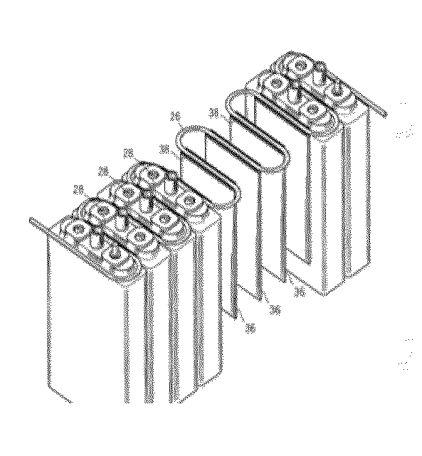
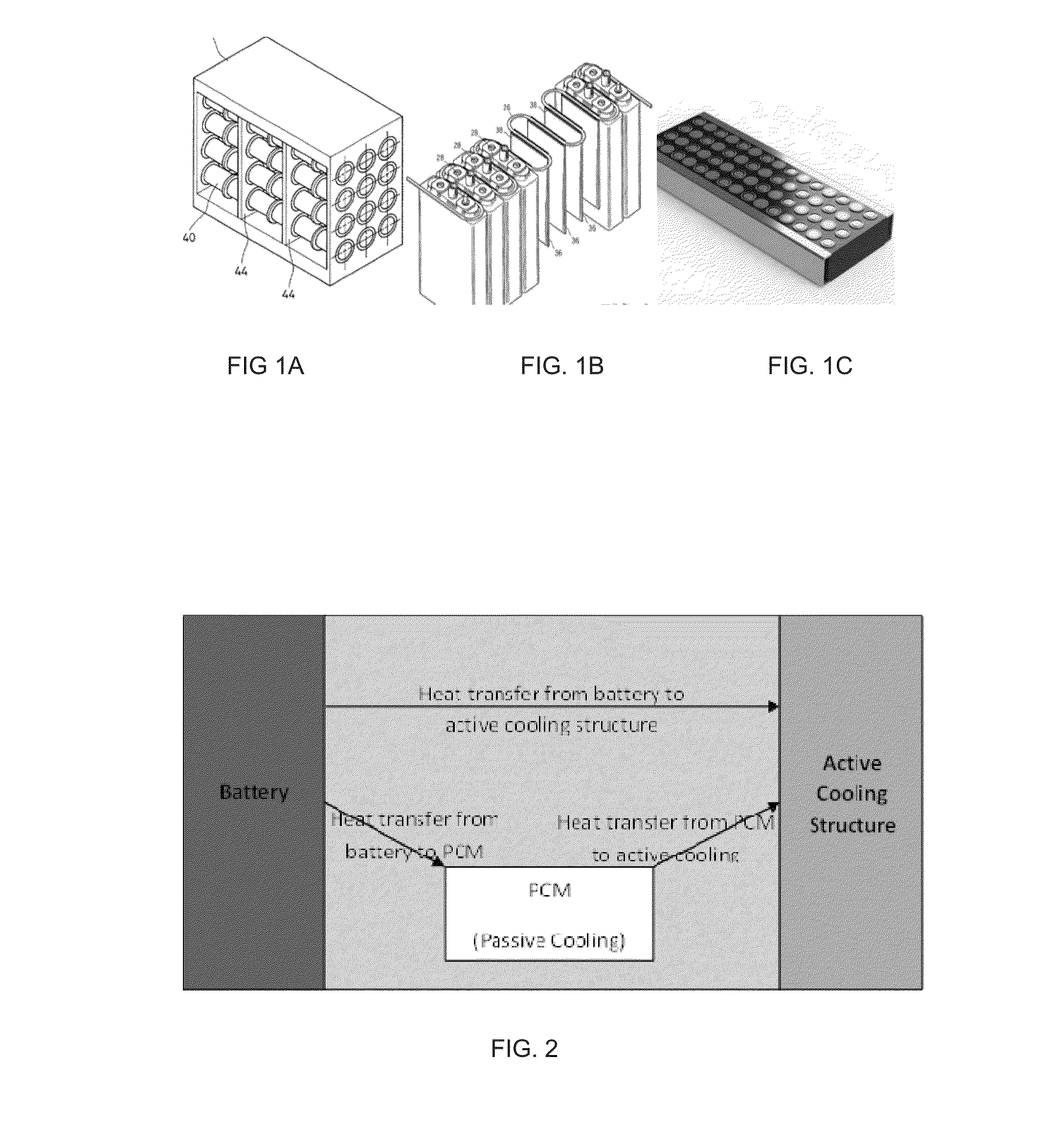
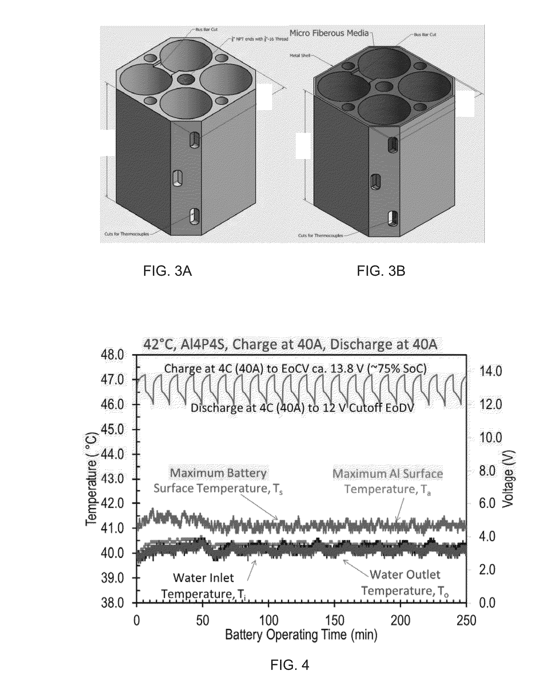
[0075]Multiple battery packs were assembled to hold 16 batteries electrically connected in 4p4s (4 paralleled series with 4 batteries in a series) pattern. Cooling water channels were introduced inside the cooling structures as shown in FIG. 1. The arrays were distinguished based on the material used to form the cooling structures: Al-block (Aluminum cooling block) and MFM-PCM (copper microfibrous media with phase change materials). Al-block is neat active cooling design; MFM-PCM is a combination of active and passive cooling approaches (see FIGS. 3a and 3b).

[0076]Table 3 compares the Al-block and MFM-PCM with other typical battery cooling structures for 16 batteries (26650 power batteries) in a 4p4s array. Table 3 shows that MFM-PCM with 70 vol. % of PCM has a comparable heat capacity compared to PCM-only devices, which is about twice the heat capacity of non-PCM devices. As a result, the 26650 batteries can be discharged at high cu...


PUM

PropertyMeasurementUnit
diameteraaaaaaaaaa
diameteraaaaaaaaaa
vol. %aaaaaaaaaa

Abstract

Thermal management systems for high energy density batteries, particularly arrays of such batteries, and methods of making and using thereof are described herein. The system includes one or more thermal conductive microfibrous media with one or more phase change materials dispersed within the microfibrous media and one or more active cooling structures. Energy storage packs or arrays which contain a plurality of energy storage cells and the thermal management system are also described. Further described are thermal or infrared shielding blankets or barriers comprising one or more thermal conductive microfibrous media comprising one or more phase change materials dispersed within the microfibrous media.

Description

CROSS-REFERENCE TO RELATED APPLICATIONS[0001]This application claims priority to U.S. Provisional Application No. 61 / 940,105, filed Feb. 14, 2014; U.S. Provisional Application No. 61 / 947,695, filed Mar. 4, 2014; U.S. Provisional Application No. 61 / 969,401, filed Mar. 24, 2014; and U.S. Provisional Application No. 61 / 979,293, filed Apr. 14, 2014, the disclosures of which are incorporated herein by reference in their entirety.FIELD OF THE INVENTION[0002]This invention is in the field of thermal management systems for energy storage cells having high charge / discharge currents, such as batteries and other electronic devices.BACKGROUND OF THE INVENTION[0003]Rechargeable batteries, especially high-energy-density lithium-ion (“Li-ion”) batteries, have been used in a variety of applications, such as power trains of electric vehicles (EVs) and hybrid electric vehicles (HEVs), consumer electronics, such as electric appliances, and aerospace and military applications due to their high energy d...

Claims


Application Information

Patent Timeline
Patent Type & Authority Applications(United States)
IPC IPC(8): H01M10/625H01M50/213H01M50/222H01M50/224H01M50/227H01M50/229H01M50/233
CPCH01M10/625H01M10/613H01M10/653H01M10/052H01M10/659H01M2220/20H01M10/658H01M10/6557H01M10/6567Y02E60/10H01M50/24H01M50/229H01M50/224H01M50/233H01M50/213H01M50/222H01M50/227
Inventor YANG, HONGYUNTATARCHUK, BRUCE J.BARRON, TROY J.DIMICK, PAUL S.
Owner INSTREETCARICRON
Learn More