Lighting device with a LED and an improved reflective collimator

Inactive Publication Date: 2015-08-06
KONINKLIJKE PHILIPS ELECTRONICS NV
View PDF49 Cites 21 Cited by
  • Summary
  • Abstract
  • Description
  • Claims
  • Application Information

AI Technical Summary

Benefits of technology

The invention is a lighting device that is small and has good collimation. It also helps to dissipate heat better, which is an improvement over existing lighting devices.

Problems solved by technology

Furthermore, in a collimator comprising only reflective segments, the central segments (i.e. close to the optical axis or optical plane) extend almost parallel to the main direction thus rendering said collimator to be relatively deep and thus to have an unfavorable high aspect ratio.

Method used


Image

  • Lighting device with a LED and an improved reflective collimator
  • Lighting device with a LED and an improved reflective collimator
  • Lighting device with a LED and an improved reflective collimator

Examples


Embodiment Construction

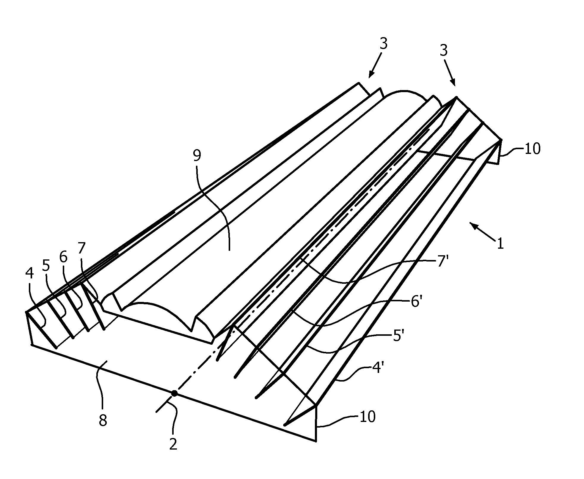
[0042]In FIG. 1, a first embodiment of a lighting device 1 according to the present invention with very compact design is depicted. The lighting device has a light source connector comprising a plurality of LEDs (not shown in detail), which are positioned on straight (dotted) line 2. During operation of the lighting device, the plurality of LEDs emits light in a main direction, defining an optical plane (not shown) which extends perpendicular to substrate 8 on which the LEDs are positioned. In this embodiment, substrate 8 represents the housing of the light device. If needed, the substrate can also be occupied in a bowl- or box-shaped housing. The necessary wiring and driver electronics needed for driving the LEDs is not shown for clarity. They may be attached to or incorporated in substrate 8 or on a sub mount on which substrate 8 may be positioned.

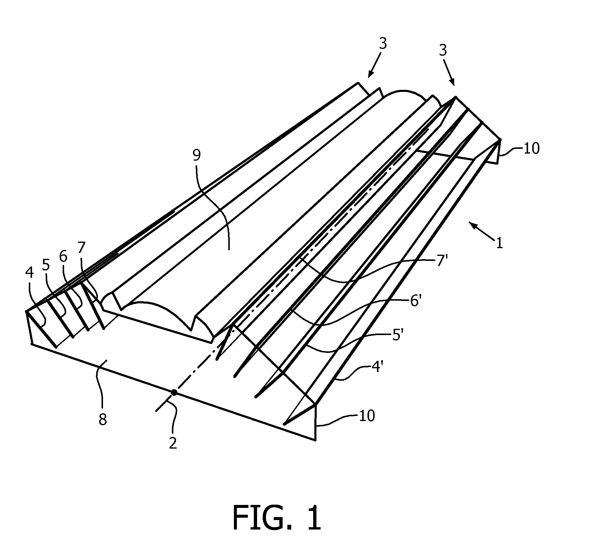
[0043]Lighting device 1 further comprises a reflective collimator 3, being composed of a plurality of reflective segments 4, 4′, 5, 5′,...


PUM

PropertyMeasurementUnit
Dielectric polarization enthalpyaaaaaaaaaa
Electrical conductoraaaaaaaaaa
Transparencyaaaaaaaaaa

Abstract

The invention relates to a lighting device (1) comprising a housing (8) with a light source connector for a LED (11) and a reflective collimator (3) and a refractive collimator (9) as well as to a method for their manufacture. The reflective collimator (3) comprises a plurality of reflective segments (4, 4′, 5, 5′, 6, 6′, 7, 7′), which are spaced apart from each other by means of air slits suitable for dissipation of heated air. The segments (4, 4′, 5, 5′, 6, 6′, 7, 7′) are adapted to reflect laterally emitted light generated by the light source (11) towards a direction which is substantially parallel to said main direction. Lighting devices according to this invention may have a compact design and an improved dissipation of the heat generated by the LEDs.

Description

FIELD OF THE INVENTION[0001]The present invention relates to a lighting device comprising a housing with a light source connector adapted to contain at least one LED for emitting light in a main direction and a reflective collimator connected to the housing. The invention also relates to a method for the manufacture of such lighting device.BACKGROUND OF THE INVENTION[0002]A lighting device of the in the opening paragraph mentioned type is known as such. For example, the U.S. Pat. No. 7,891,842-B2 discloses a lighting device with a LED positioned in a housing and a reflector attached to this housing. The reflector is designed as a generally truncated conical body which may substantially collimate the light emitted by the LED. A plurality of ventilation openings are formed in the reflective surface of the reflector body. These ventilation openings allow for dissipation of heat generated by the LED during operation of the lighting device. In order to improve the heat dissipation, an an...

Claims


Application Information

Patent Timeline
IPC IPC(8): F21V7/04F21V29/51F21V29/60F21V5/04F21V29/505
CPCF21V29/505F21V29/673F21V29/677F21V29/83F21V5/045F21V7/0025F21V7/04F21Y2101/02F21Y2103/003F21V29/51F21V29/60F21V5/04F21V7/0083F21V7/00F21Y2101/00F21Y2103/00F21Y2103/10F21Y2115/10Y10T29/49117
Inventor DROSS, OLIVERKADIJK, SIMON EME
Owner KONINKLIJKE PHILIPS ELECTRONICS NV
Why Eureka
Try Eureka