
Lighting device, lens, system and method

a technology of light source and optical device, applied in the field of light source, can solve the problems of distorted pattern at the perimeter, and achieve the effect of enhancing the desired effect of homogenization, reducing the overall thickness of the optical device, and sufficient randomizing

Inactive Publication Date: 2015-08-06
SIGNIFY HLDG BV
View PDF3 Cites 8 Cited by
  • Summary
  • Abstract
  • Description
  • Claims
  • Application Information

AI Technical Summary

Benefits of technology

This patent is about a new technology for making optics out of thin, transparent foils with a micro-structured surface. This technology allows for low-cost manufacturing using hot embossing and roll-to-roll processing. The advantages of this technology include its ability to produce optics with a limited height, which can be useful in a variety of applications.

Problems solved by technology

Said transition surfaces may not be perfectly formed and hence may not extend perfectly steep, however, these transition surfaces are not to be considered as separate facets.
Furthermore, each facet has a perimeter edge by which it borders its adjacent facet, said perimeter edge is a source for distortion of the displayed pattern.

Method used


Image

  • Lighting device, lens, system and method
  • Lighting device, lens, system and method
  • Lighting device, lens, system and method

Examples


first embodiment

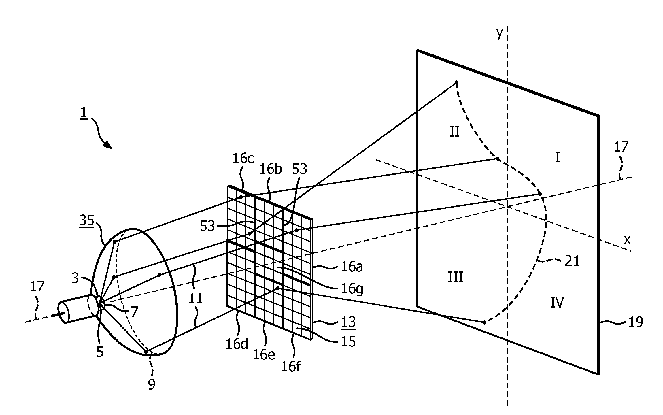
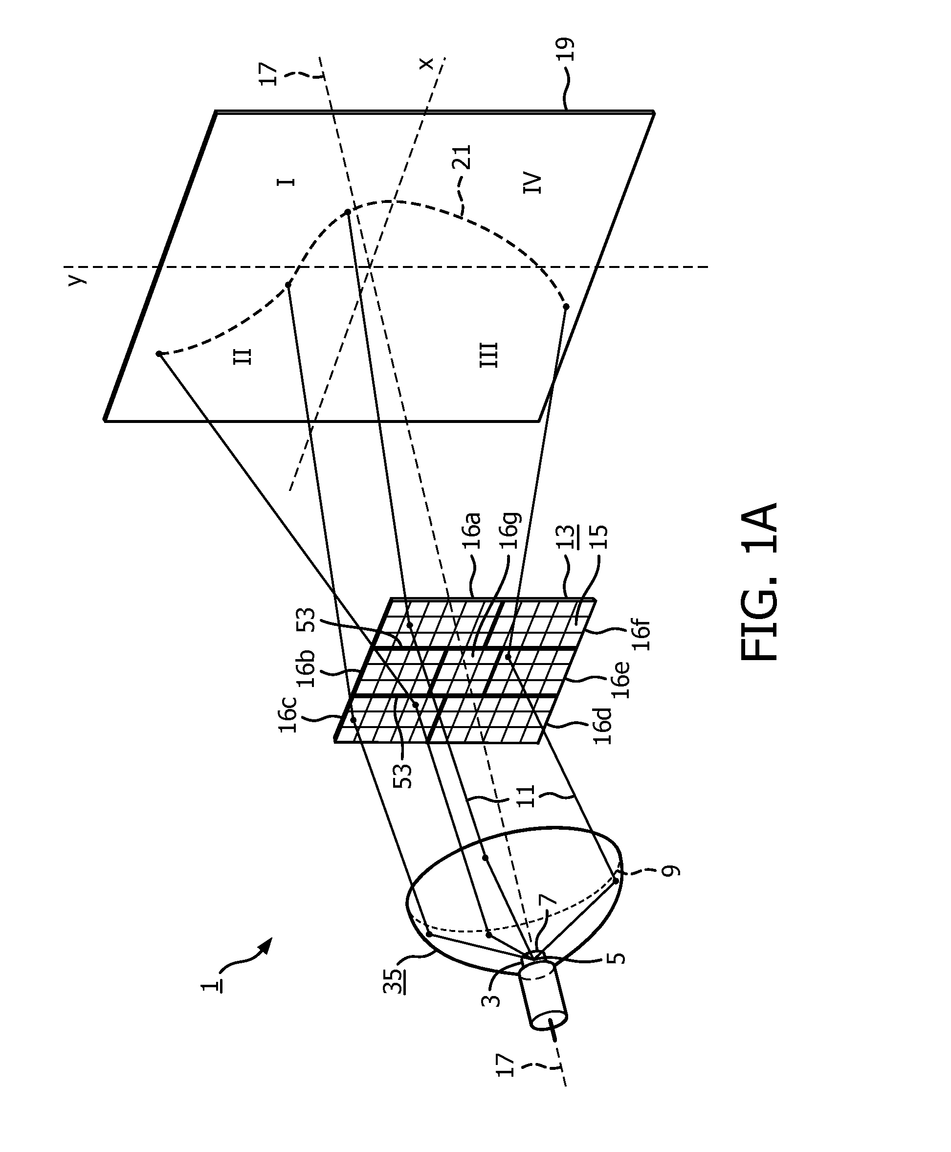
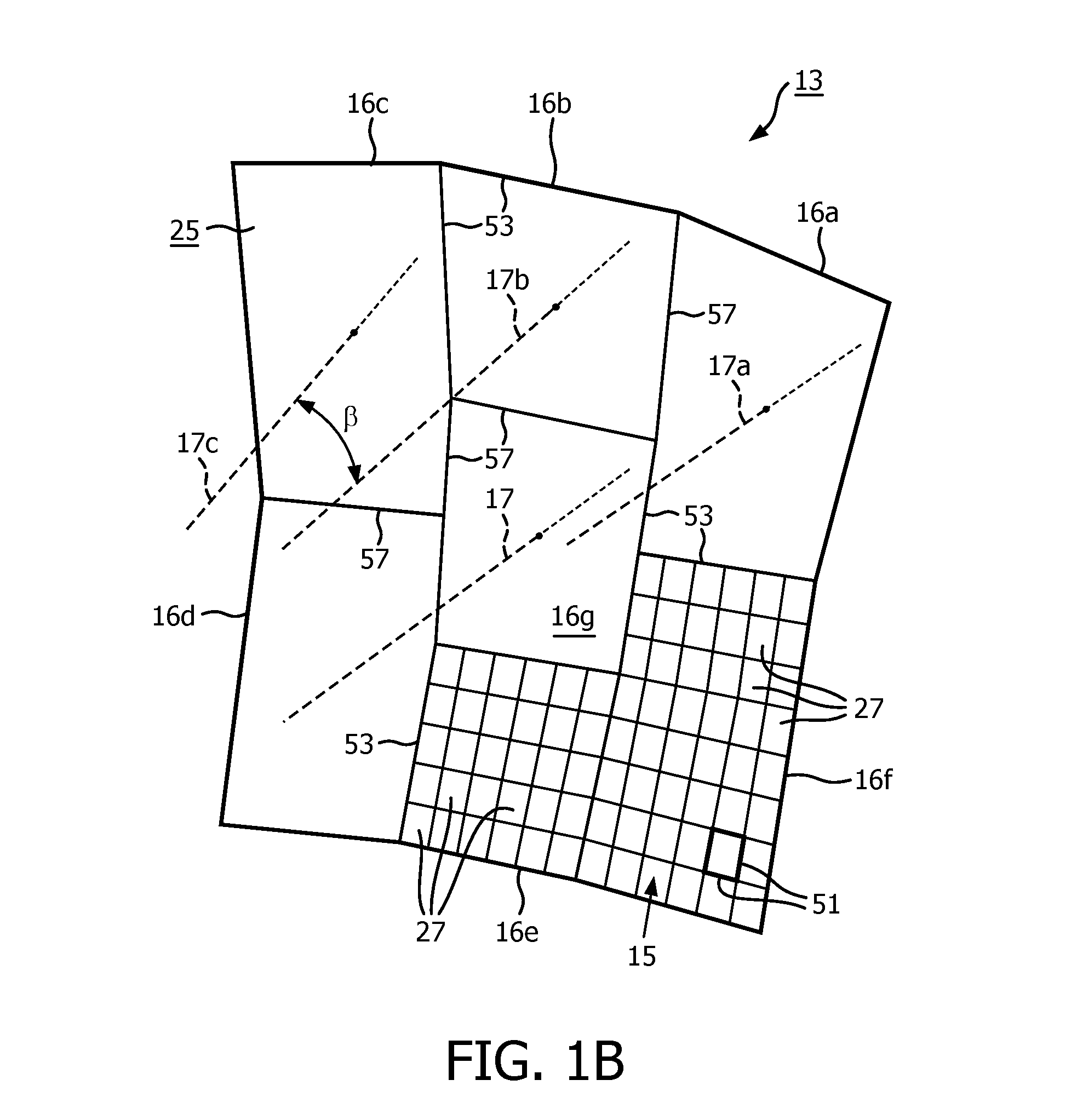
[0054]Referring now to the drawings, where like reference numerals designate like elements, there is shown in FIG. 1A a schematic perspective view of a lighting device 1 according to the invention. The lighting device comprises a lamp / reflector unit 35 as a light source 3 with a light emitting element 5, preferably a point-shaped light, for example a LED, or a high pressure gas discharge lamp, such as a UHP-lamp, positioned in a focal point 7 of a reflector body 9. The lamp / reflector unit, during operation, generates a parallel beam of light 11 which subsequently is incident on a transparent optical device 13. Said optical device being positioned transverse to the parallel beam and comprises a plurality of facets 15 sub-divided into at least a first 16a and a second group of facets 16b and further groups of facets 16c-16g, which facets for the sake of simplicity are shown as squares, the average orientation of the facet surfaces defines an optical axis 17. Each group of facets has a...

second embodiment

[0056]FIG. 2 shows a schematic side view of a lighting device 1 according to the invention. The lighting device comprises a lamp / reflector unit 35 as a light source 3 with a light emitting element 5 positioned in a reflector body 9. The lamp / reflector unit, during operation, generates a converging beam of light 11 which subsequently is incident on a reflective optical device 13. Said optical device comprises a plurality of facets, the average orientation of the facets defines an optical axis 17. The plurality of facets are sub-divided into a first 16a, a second 16b, third 16c and fourth group of facets 16d. Each group of facets has a respective group optical axis 17a-17d, of said axes at least one pair is mutually angled by an angle β, β′ of at least 5°, in the figure between group optical axes 17a-17b β=15° and between group optical axes 17c-17d β′=10°. Each facet redirects via reflection a light beam (or light ray) incident on said facet in a specific direction towards a display s...


PUM

PropertyMeasurementUnit
sizeaaaaaaaaaa
sizeaaaaaaaaaa
energyaaaaaaaaaa

Abstract

A lighting device comprising at least four optical devices. Each optical device has an associated light source and comprises a first surface with a plurality of micro sized facets. Each facet has a respective orientation and said plurality of facets has an optical axis which extends parallel to the normal vector to an average orientation of all said respective orientations. The optical devices are divided over at least two sets of optical devices which are designed to mutually issue a different pattern during operation as the optical devices of different sets are arranged in a mutually alternating manner.

Description

FIELD OF THE INVENTION[0001]The present invention relates to a lighting device with micro sized facets.BACKGROUND OF THE INVENTION[0002]Conventional techniques for homogenizing light make use of arrayed micro-lenses, diffractive diffusers, ground glass diffusers, and holographically-generated diffusers. Micro-lens arrays homogenize light by creating an array of overlapping diverging cones of light. Each cone originates from a respective micro-lens and diverges beyond the focal spot of the lens. In the conventional arrays, the individual lenses are identical to each other. Ground glass diffusers are formed by grinding glass with an abrasive material to generate a light-scattering structure in the glass surface.[0003]Micro-lens arrays, ground glass diffusers and holographic diffusers all have the disadvantage of not being able to control the angular spread of the homogenized, diverging light. Light in general has an angular spread that is fairly uniform over a desired angular region, ...

Claims


Application Information

Patent Timeline
Patent Type & Authority Applications(United States)
IPC IPC(8): F21V5/00F21V7/00F21S8/10
CPCF21S48/1225F21S48/1323F21S48/1376G02B19/0066F21Y2101/02F21S48/1705F21V5/007F21V7/00F21W2101/10F21S48/1208F21S41/00F21S41/275F21S41/285F21W2102/00F21S41/321F21S41/337F21W2102/135F21Y2115/10F21S41/29F21S41/60Y10T29/49826
Inventor MICHIELS, WILHELMUS PETRUS ADRIANUS JOHANNUSDE ZWART, SIEBE TJERKKRIJN, MARCELLINUS PETRUS CAROLUS MICHAEL
Owner SIGNIFY HLDG BV
Learn More