Electronic Apparatus and Control Method for High Frequency AC to DC Conversion

a technology of electronic apparatus and control method, applied in the direction of power electronics conversion, power conversion system, climate sustainability, etc., can solve the problems of poor power factor, poor power transfer capability, poor power factor, etc., and achieve the effect of small switching loss and easy fabrication into a single integrated circuit (ic)

Active Publication Date: 2015-07-23
THE UNIVERSITY OF HONG KONG
View PDF2 Cites 5 Cited by
  • Summary
  • Abstract
  • Description
  • Claims
  • Application Information

AI Technical Summary

Benefits of technology

The present invention provides a solution for high frequency AC to DC conversion with power factor correction. The invention uses a resonance technique to shape the AC line current and achieve a near unity power factor. The output voltage of the converter can be controlled above or below the AC line voltage. All the semiconductor devices operate at a constant frequency that matches the frequency of the AC source. The control scheme is simple and can be implemented using analog and digital circuits, making it suitable for IC fabrication.

Problems solved by technology

There is a lack of research examining and addressing the problems arising from the receiver side, which also has a significant influence on the performance and efficiency of the system.
These diode rectifiers draw highly distorted current from the AC source and result in a poor power factor (PF).
The energy efficiency and power transfer capability of a poor PF system are relatively low because of the high conduction loss in the power converters and transmission wires.
Additionally, the distorted current has rich harmonic content which may create extra electromagnetic interference (EMI) in neighboring electronic equipment.
In fact, when the switching frequency approaches tens of megahertz, the switching loss becomes significance and the efficiency of the converter is sharply reduced.
The converter also has a number of other problems and limitations, including parasitic inductance and capacitance of the interconnections, stray inductances of the magnetic components, and parasitic and junction capacitances of the semiconductor diodes and switches.
The EMI, thermal, insulation and isolation problems of the converter are not easy to solve individually.
Hence, the conventional current-shaping PFC technology is not suitable for high frequency ac system since the fundamental frequency is already in the range of hundreds of kilohertz to a few megahertz.

Method used


Image

  • Electronic Apparatus and Control Method for High Frequency AC to DC Conversion
  • Electronic Apparatus and Control Method for High Frequency AC to DC Conversion
  • Electronic Apparatus and Control Method for High Frequency AC to DC Conversion

Examples


Embodiment Construction

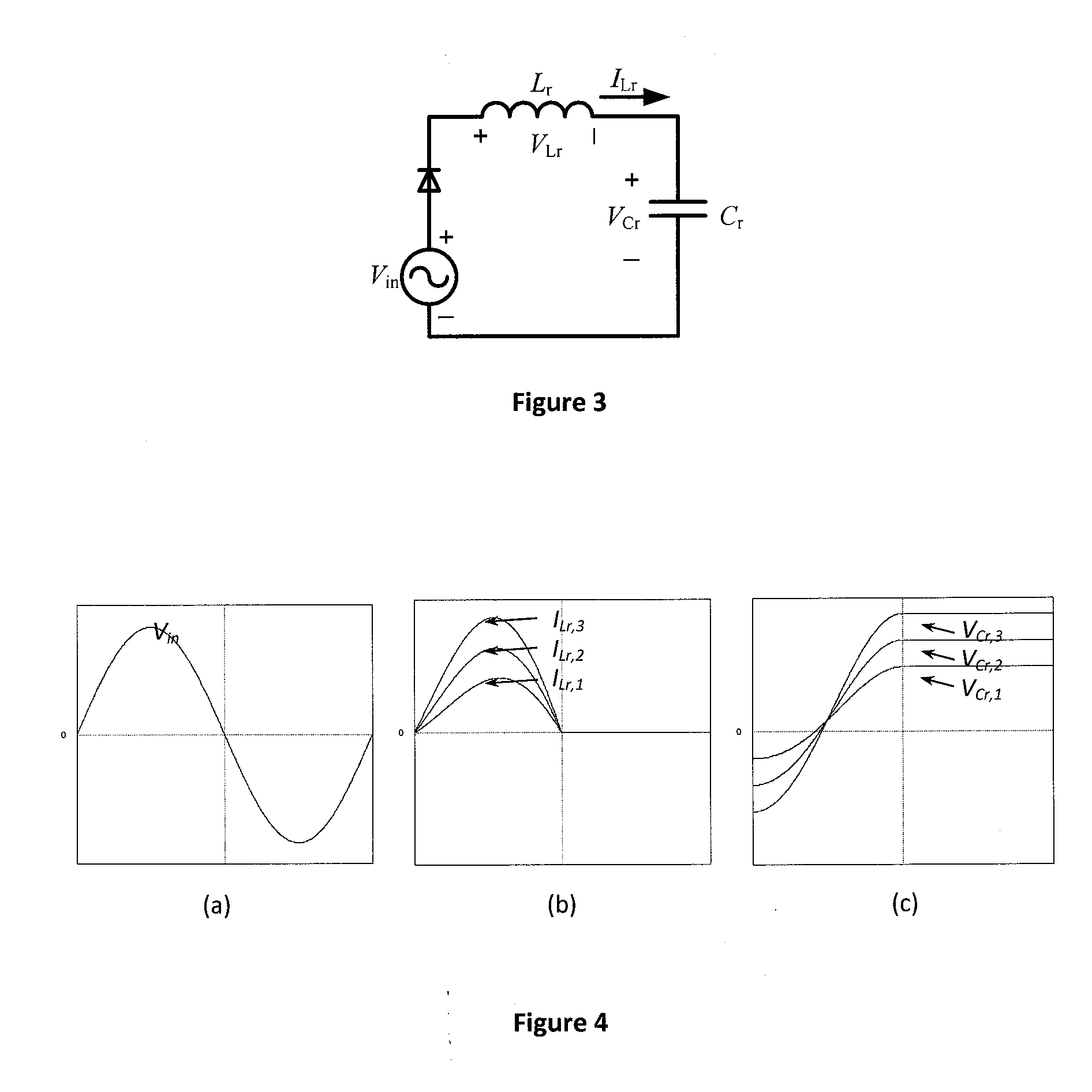
[0023]According to the present invention, a new concept is proposed to realize high frequency AC to DC conversion with input AC side power factor correction (PFC) and output DC voltage regulation. Considering a half wave rectifier with an inductive-capacitive (LC) load as shown in FIG. 3. The voltage source Vin is ac and its angular frequency is ω. A LC load is selected such that its angular resonance frequency ωr=1 / (2 π{square root over (LrCr)}) is equal to the angular frequency of the source. For the positive half-cycle of the source in this circuit, the diode is forward biased. The current produced by the LC resonance will be forced into a sinusoidal form. The power flow is controlled by the characteristic impedance Zr={square root over (LrCr)} and the initial condition of the capacitor VCr,0. FIGS. 4(a)- 4(c) depict the input voltage and corresponding current and voltage waveforms, respectively, of the rectifier under different initial values of the capacitor. For the negative h...


PUM


Abstract

A high-frequency ac-dc power converter takes an input ac signal and converts it to an output dc signal. The converter has at least two front-end rectifier diodes arranged as a full wave rectifier of the input ac signal. A first inductor positioned at the output of the full wave rectifier. An output capacitor is connected across a load for the converter. There are at least one additional inductor and one additional capacitor. A switching circuit selectively forms different (LC) resonant circuits with the inductors and capacitors during a cycle of the input ac signal to form a dc-dc power converter.

Description

FIELD OF THE INVENTION[0001]The present invention relates generally to high frequency AC to DC conversion for the purpose of wireless power transfer.BACKGROUND OF THE INVENTION[0002]Wireless power transfer (WPT) based on the magnetic resonance and near-field coupling of two loop resonators was reported by Nicola Tesla a century ago. It transmits electric energy and information from a transmitter to the receiver without physical contact. Since the 1960s, and particularly over the last few decades, WPT has been an active research area in regard to transcutaneous energy systems for medical implants. For modern short-range applications, inductive power transfer (IPT) systems and wireless charging systems for portable electronic equipment have attracted much attention since 1990's and 2000's respectively. Wireless charging technology for portable electronic devices has reached commercialization stage through the launch of the “Qi” Standard by the Wireless Power Consortium, now comprising...

Claims


Application Information

Patent Timeline
Patent Type & Authority Applications(United States)
IPC IPC(8): H02M1/42H02J5/00H02M7/06
CPCH02M1/4266H02J5/005H02M7/066H02M1/4241Y02B70/10H02J50/12
Inventor KWAN, LEE CHIKIRATIPONGVOOT, SITTHISAK
Owner THE UNIVERSITY OF HONG KONG
Why Eureka
Try Eureka