Systems for determining and imaging wax deposition and simultaneous corrosion and wax deposit determination in pipelines

a technology of wax deposition and imaging system, which is applied in the direction of neutron radiation measurement, instruments, radiation measurement, etc., can solve the problems of difficult prediction of deposit thickness, very costly paraffin and asphalt deposition in crude oil transportation, and stop oil production, so as to increase the probability of neutron capture

Active Publication Date: 2015-07-16
KING ABDULAZIZ UNIV
View PDF5 Cites 3 Cited by
  • Summary
  • Abstract
  • Description
  • Claims
  • Application Information

AI Technical Summary

Benefits of technology

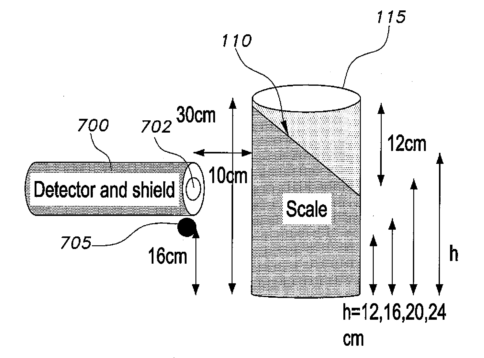
[0007]The systems for determining and imaging wax deposition and simultaneous corrosion and wax deposit determination in pipelines relates to a system for determining wax deposition and corrosion by one or both of two techniques. In both techniques, a source of neutron radiation is directed at the pipeline. In one technique, a neutron detector surrounded by an absorption shield defining a collimation window counts neutrons reflected back to the detector by back diffusion or backscatter radiation. In the other technique, a gamma ray detector measures gamma rays emitted when the emitted neutrons are absorbed in the pipeline. A neutron moderator-reflector is placed around the pipeline to increase the likelihood of neutron capture.

Problems solved by technology

Paraffin and asphalt deposition in crude oil transport is a very costly problem in oil industry.
The accumulation of wax on the inner surface of pipes reduces flow and may cause a blockage in a pipeline that may stop oil production.
Prediction of deposit thickness is very difficult due to the complex compositions of crude oil.
Wax deposition in pipelines can be very costly for plant operation in the oil industry.

Method used


Image

  • Systems for determining and imaging wax deposition and simultaneous corrosion and wax deposit determination in pipelines
  • Systems for determining and imaging wax deposition and simultaneous corrosion and wax deposit determination in pipelines
  • Systems for determining and imaging wax deposition and simultaneous corrosion and wax deposit determination in pipelines

Examples


Embodiment Construction

[0023]The systems for determining and imaging wax deposition and simultaneous corrosion and wax deposit determination in pipelines relate to techniques in which a source of neutron radiation is directed at the pipeline. In a first technique, a neutron detector surrounded by an absorption shield defining a collimation window counts neutrons reflected back to the detector by back diffusion or backscatter radiation. In the other technique, a gamma ray detector measures gamma rays emitted when the emitted neutrons are absorbed in the pipeline. A neutron moderator-reflector like water is placed around three sides, e.g., top, left, and bottom portions of the pipeline to increase the likelihood of neutron capture. The system will be illustrated in the following examples.

[0024]Two types of hydrocarbon scale were investigated, namely, asphalt and paraffin wax, having specific gravities of 2.0 and 0.9, respectively. Actual organic scale is usually a mixture of these materials, and also contai...


PUM

PropertyMeasurementUnit
thickaaaaaaaaaa
thicknessaaaaaaaaaa
thicknessaaaaaaaaaa

Abstract

The systems for determining and imaging wax deposition and simultaneous corrosion and wax deposit determination in pipelines relate to systems for determining wax deposition and corrosion by one or both of two techniques. In both techniques, a source of neutron radiation is directed at the pipeline. In one technique, a neutron detector surrounded by an absorption shield defining a collimation window counts neutrons reflected back to the detector by back diffusion or backscatter radiation. In the other technique, a gamma ray detector measures gamma rays emitted when the emitted neutrons are absorbed in the pipeline. A neutron moderator-reflector is placed around three sides of the pipeline to increase the likelihood of neutron capture.

Description

CROSS-REFERENCE TO RELATED APPLICATION[0001]This application claims the benefit of U.S. Provisional Patent Application Ser. No. 61 / 927,950, filed Jan. 15, 2014.BACKGROUND OF THE INVENTION[0002]1. Field of the Invention[0003]The present invention relates to the determination of the extent of deposition of wax and / or corrosion in a pipeline, and particularly to a system for determining and imaging wax deposition and corrosion in a pipeline that uses a neutron source, neutron and / or gamma ray detectors, and backscatter diffusion collimation.[0004]2. Description of the Related Art[0005]Paraffin and asphalt deposition in crude oil transport is a very costly problem in oil industry. The accumulation of wax on the inner surface of pipes reduces flow and may cause a blockage in a pipeline that may stop oil production. Prediction of deposit thickness is very difficult due to the complex compositions of crude oil. At or below the Wax Appearance Temperature (WAT), hydrocarbon molecules crystal...

Claims


Application Information

Patent Timeline
Patent Type & Authority Applications(United States)
IPC IPC(8): G01N23/204G01T3/08G01T1/24G01N17/04G01N23/00
CPCG01N23/204G01N17/04G01T3/08G01T1/24G01N23/005
Inventor ALZAIDI, SAMIR ABDUL-MAJID
Owner KING ABDULAZIZ UNIV
Why Eureka
Try Eureka