Cold storage heat exchanger

a heat exchanger and cold storage technology, applied in indirect heat exchangers, lighting and heating apparatus, transportation and packaging, etc., can solve the problems of lowering heat conduction, affecting the efficiency of cold storage medium, so as to reduce heat conduction and avoid container deformation.

Active Publication Date: 2015-07-16
DENSO CORP
View PDF5 Cites 13 Cited by
  • Summary
  • Abstract
  • Description
  • Claims
  • Application Information

AI Technical Summary

Benefits of technology

[0006]One of disadvantages to be solved of the cold storage heat exchanger is volume change of the cold storage medium caused by temperature change. Volume of the cold storage medium varies as temperature changes. On the other hand, it is desirable that the cold storage medium is accommodated in a sealed container. As the container is deformed by volume change of the cold storage medium, there may be disadvantages such as lowering of heat conduction, and leakage of the cold storage medium. Therefore, it is desirable that deformation of the container is avoided.

Problems solved by technology

One of disadvantages to be solved of the cold storage heat exchanger is volume change of the cold storage medium caused by temperature change.
As the container is deformed by volume change of the cold storage medium, there may be disadvantages such as lowering of heat conduction, and leakage of the cold storage medium.
One of disadvantages to be solved of the cold storage heat exchanger is speed of cold storage.
In one of viewpoints, it is considered that a cold storage speed is spoiled, since both an outer wall of the refrigerant pipe and an outer wall of the cold-storage-medium container may become barriers of heat conduction between a refrigerant and the cold storage medium.
One of disadvantages to be solved of the cold storage heat exchanger is a positioning between the refrigerant pipe and the cold-storage-medium container.

Method used


Image

  • Cold storage heat exchanger
  • Cold storage heat exchanger
  • Cold storage heat exchanger

Examples


first embodiment

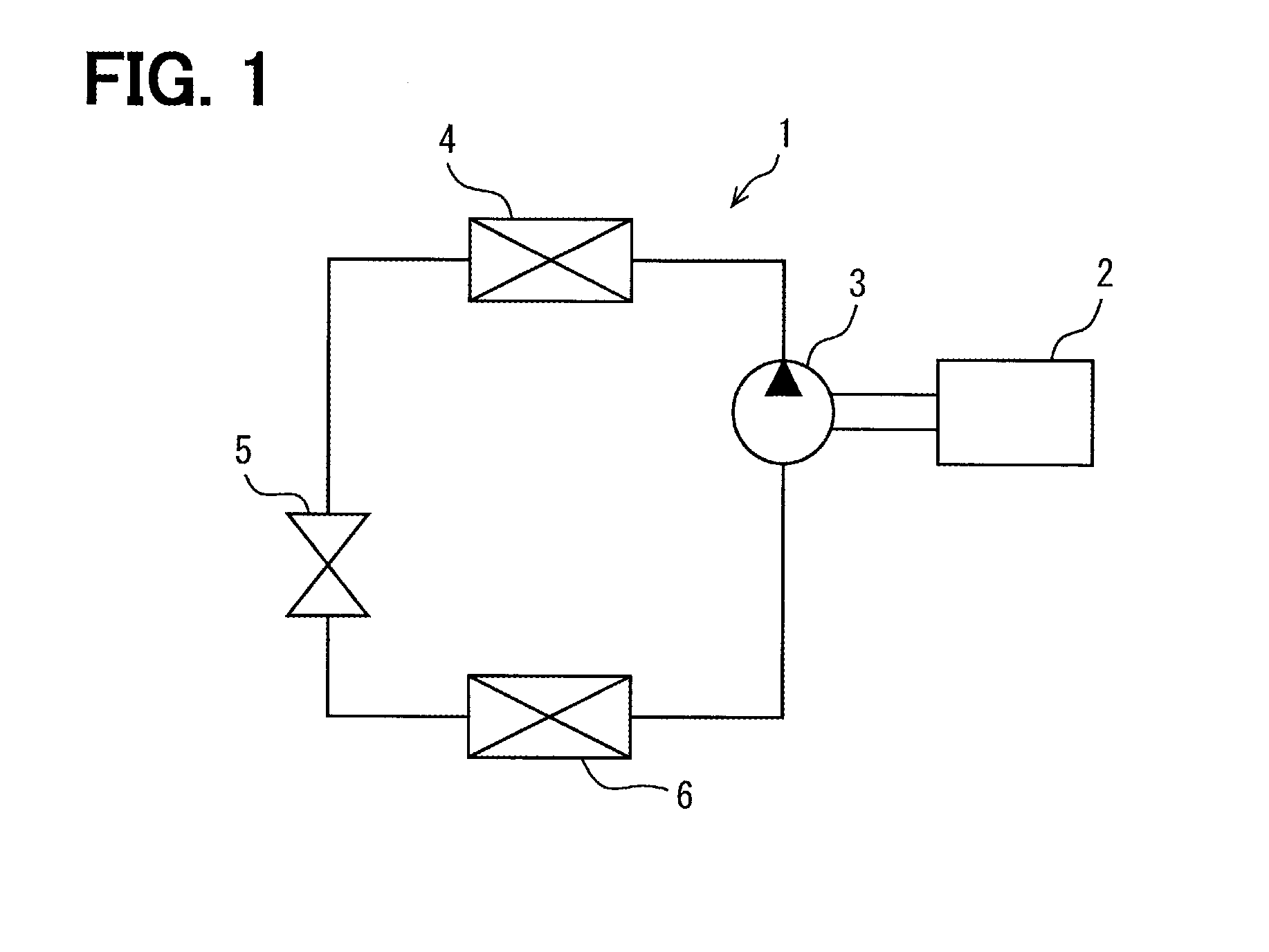
[0045]FIG. 1 is a block diagram showing a configuration of a refrigeration cycle according to a first embodiment of the present invention. The refrigeration cycle 1 is used for an air-conditioner for a vehicle. The vehicle may have a power source 2 mounted on the vehicle. The power source 2 is an internal combustion engine for driving the vehicle or an electric motor for driving the refrigeration cycle 1. The refrigeration cycle 1 has a compressor 3, a radiator 4, a reducer 5, and an evaporator 6. Those components are connected in a closed circuit by conduits and provide a refrigerant recirculation path.

[0046]The compressor 3 is driven by the power source 2. Accordingly, if the power source 2 stops, the compressor 3 also stops. The compressor 3 sucks and compresses a refrigerant from the evaporator 6, and discharges a compressed refrigerant to the radiator 4. The radiator 4 cools a high temperature refrigerant. The radiator 4 is also called as a condenser. The reducer 4 decompresses...

second embodiment

[0090]FIG. 9 shows a second embodiment which uses the above-mentioned embodiments as base structure. In the preceding embodiments, the projections 36 and 37 in truncated cone shapes are used. Alternatively, depressions with various shapes may be used. The cold-storage-medium container 30 of this embodiment has a depression 236 in a long and slender ellipse shape. The depression 236 is an ellipse shape extending in an inclined manner with respect to both the height direction Y and the width direction Z of the evaporator 6. In the preceding embodiment, the closed type depression 37 is used together. Alternatively, the cold-storage-medium container 30 of this embodiment has only the open type depression 236. It is possible to provide a cold storage heat exchanger with a quick cold storage speed.

third embodiment

[0091]FIG. 10 shows a third embodiment which uses the above-mentioned embodiments as base structure. In the preceding embodiments, only the side plate portions 31 and 32 provide the cold-storage-medium container 30. Alternatively, in this embodiment, the inner fin 60 is used additionally. The inner fin 60 is arranged inside the cold-storage-medium container 30. The inner fin 60 promotes heat conduction to the cold storage medium 50. The inner fin 60 is being pinched between the side plate portions 31 and 32 and fixed. The inner fin 60 is brazed on the side plate portions 31 and 32.

[0092]The side plate portions 31 and 32 have an open type depression 336 and a closed type depression 337. Top portion of these depressions 336 and 337 are joined to the inner fin 60 without being joined each other. This embodiment may also use only the open type depression 336. It is possible to provide a cold storage heat exchanger with a quick cold storage speed.


PUM


Abstract

A cold storage heat exchanger has refrigerant pipes fins, and cold-storage-medium containers. The cold-storage-medium container is arranged next to the refrigerant pipe. A cold storage medium is accommodated in the cold-storage-medium container in order to leave an air cell, and to provide a filling ratio of less than 90%. The cold-storage-medium container has a plurality of depressions at an inside of the cold-storage-medium container. The depression is a dimple. The plurality of depressions are joined each other at top parts and provide high rigidity. The cold-storage-medium container is positioned on the refrigerant pipe by an engaging projection. An open end of an open depression is covered by the refrigerant pipe. The cold storage medium can flow into the open depression. Therefore, the cold storage medium may directly contact the refrigerant pipe, and is directly cooled with the refrigerant.

Description

CROSS REFERENCE TO RELATED APPLICATIONS[0001]This application is a U.S. National Phase Application under 35 U.S.C. 371 of International Application No. PCT / JP2013 / 003856 filed on Jun. 20, 2013 and published in Japanese as WO 2014 / 024375 on Feb. 13, 2014. This application is based on and claims the benefit of priority from Japanese Patent Application No. 2012-175184 filed on Aug. 7, 2012. The entire disclosures of all of the above applications are incorporated herein by reference.BACKGROUND[0002]1. Technical Field[0003]The present invention relates to a cold storage heat exchanger which may be used for a refrigerating cycle.[0004]2. Background Art[0005]As shown in PLT1-PLT3, cold storage heat exchangers are known. The cold storage heat exchanger is provided by adding a cold storage medium on an evaporator which is one of heat exchanger for a refrigerating cycle. The cold storage heat exchanger has a cold-storage-medium container to be disposed to contact on a refrigerant passage pipe...

Claims


Application Information

Patent Timeline
Patent Type & Authority Applications(United States)
IPC IPC(8): F28D20/00
CPCF28D20/0034B60H1/32F28D1/053F28D20/021F28D1/05366F28D20/02F28D2020/0013Y02E60/14F28D2020/0008
Inventor KITOH, YUUSUKENAGASAWA, TOSHIYATORIGOE, EIICHIOTA, AUNABEI, JUNHASEBA, DAISUKE
Owner DENSO CORP
Why Eureka
Try Eureka