Multi-photon microscope having an excitation-beam array

a multi-photon microscope and beam array technology, applied in the field of microscopy, can solve the problems of reducing the efficiency of scanning, and reducing the number of photons collected, so as to reduce the complexity and cost, reduce crosstalk, and keep the average optical power delivered to brain tissue within a tolerable level.

Active Publication Date: 2015-06-11
THE BOARD OF TRUSTEES OF THE LELAND STANFORD JUNIOR UNIV
View PDF0 Cites 7 Cited by
  • Summary
  • Abstract
  • Description
  • Claims
  • Application Information

AI Technical Summary

Benefits of technology

[0010]An illustrative embodiment comprises a two-photon microscopy imaging system that employs an optical system that provides a plurality of laser beamlets arranged such that give rise to a two-dimensional array of optical spots (i.e., foci) at an image region that defines a first plane, where the array includes a plurality of rows of foci. The beamlets simultaneously excite fluorescence at a two-dimensional array of locations that are distributed throughout the image region. The imaging system linearly scans the beamlet array across the image region in a first direction, where the beamlet array is oriented with respect to the first direction such that each of its rows forms an angle to the first direction. The angle, the number of beamlets, and the beamlet spacing within each row are selected so that adjacent beamlets in each row are staggered along the spacing between the rows in the direction orthogonal to the scan direction. As a result, high-resolution scanning of the entire image region during a single linear scan of the beamlet array is enabled, where each beamlet interrogates a different linear sub-region of the total image region. Further, a large image region can be interrogated in the same amount of time required to scan each much smaller imaging sub-region. Because the entire image region is scanned during each linear scan of the beamlet array, only a single-axis scanner is required. Embodiments of the present invention, therefore, have lower complexity and cost than multi-photon microscopy systems of the prior art.
[0011]In some embodiments, the angle, the number of beamlets, and the beamlet spacing within each row are selected so that adjacent beamlets in each row are substantially evenly distributed along the spacing between the rows in the direction orthogonal to the scan direction. In some embodiments, the spacing of the beamlets and the angle of rotation of the array are selected such that the spacing between adjacent scan lines is sufficiently small to achieve micron-level image resolution, while also keeping the spacing between the spots large enough to mitigate crosstalk.
[0012]In some embodiments, the excitation source is an ultrashort-pulsed regenerative fiber laser amplifier, which enables each laser pulse to have an energy higher than that provided by a Ti-Sapphire laser, which is typically used in the prior art. The higher energy of the laser pulses enables an enhanced two-photon excitation effect for each of the plurality of laser foci, yet the ultrashort-pulsed operation keeps the average optical power delivered to brain tissue within a tolerable level.

Problems solved by technology

Unfortunately, conventional two-photon microscopy technology suffers from relatively low imaging speeds (typically within the range of 10-20 Hz) because it is difficult to gather sufficient numbers of photons from each pixel at high frame rate.
Unfortunately, commercially available Ti-Sapphire lasers have an average power of only a few Watts and a repetition rate of around only 80 MHz.
Unfortunately, operation at a higher frame rate results in reduced photon collection (to only ˜1-10 photons per pixel per frame).
As a result, the deleterious effects of faster scanning on image quality and SNR generally outweigh any potential benefit.
Furthermore, in practice, scanning speed is often limited by mechanical and / or optical constraints.
Conventional single-photon epifluorescence microscopy suffers from high tissue scattering and low optical sectioning ability.
Such disadvantages can give rise to an overlap of photons emitted from different positions into the same pixel of the camera leading to significant image blur, thereby degrading image resolution.

Method used


Image

  • Multi-photon microscope having an excitation-beam array
  • Multi-photon microscope having an excitation-beam array
  • Multi-photon microscope having an excitation-beam array

Examples


Embodiment Construction

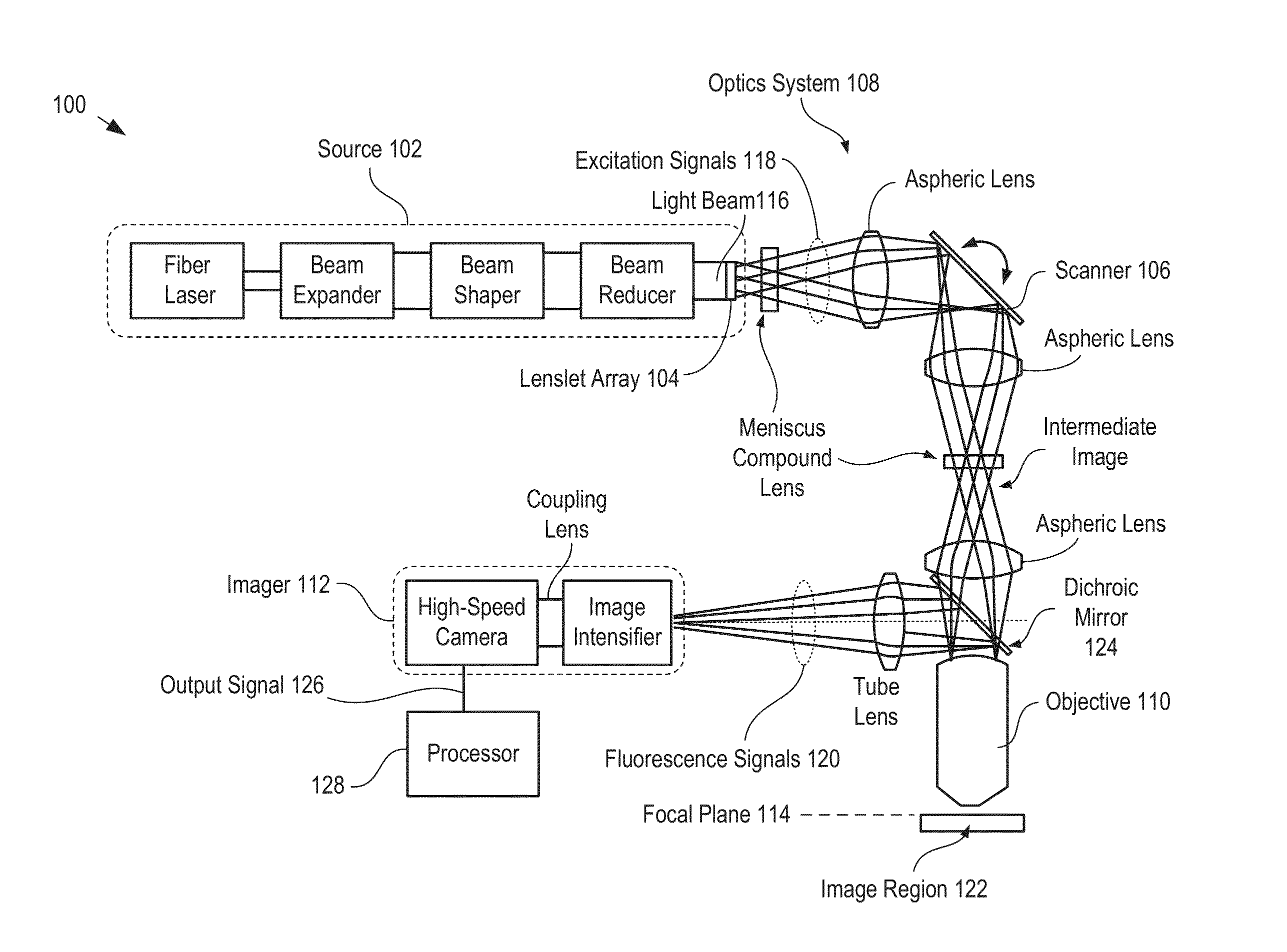
[0023]FIG. 1 depicts a schematic drawing of a portion of an imaging system in accordance with an illustrative embodiment of the present invention. Imaging system 100 is a two-photon laser-scanning microscopy system that comprises source 102, lenslet array 104, scanner 106, optics system 108, objective 110, imager 112, and processor 128. In some embodiments, imaging system 100 is a single-photon microscopy system. In some embodiments, imaging system 100 is a multi-photon microscopy system that requires more than two photons to excite a fluorophore.

[0024]FIG. 2 depicts operations of a method suitable for imaging an image region in accordance with the illustrative embodiment of the present invention. Method 200 begins with operation 201, wherein light beam 116 is provided to lenslet array 104.

[0025]Source 102 includes an ultrashort-pulsed regenerative fiber laser amplifier (hereinafter referred to as a “fiber laser”) that emits light at approximately 1030 nm (e.g., a regenerative ultra...


PUM


Abstract

A two-photon imaging system capable of imaging of an image region in real time is presented. The imaging system comprises a source of excitation light that provides the excitation light as a plurality of laser beamlets. The plurality of laser beamlets is collectively scanned by a single-axis scanner along a first direction in the focal plane of the image region and oriented such that neither the rows nor columns are aligned with the first direction. As a result, each laser beamlet scans a different sub-region of the image region and the plurality of sub-regions are simultaneously scanned. As a result, the entirety of the image region is scanned in the same amount of time required to scan one image sub-region.

Description

CROSS REFERENCE TO RELATED APPLICATIONS[0001]This case claims priority of U.S. Provisional Patent Application Ser. No. 61 / 913,695, filed Dec. 9, 2013 (Attorney Docket: 146-044PR1), which is incorporated by reference. If there are any contradictions or inconsistencies in language between this application and one or more of the cases that have been incorporated by reference that might affect the interpretation of the claims in this case, the claims in this case should be interpreted to be consistent with the language in this case.FIELD OF THE INVENTION[0002]The present invention relates to microscopy in general, and, more particularly, to multi-photon microscopy.BACKGROUND OF THE INVENTION[0003]Multi-photon microscopy is an imaging technique in which an excitation laser signal is scanned over a region of interest (i.e., image field) and fluorophores in the image field are excited only when they simultaneously absorb multiple photons of the excitation light. In two-photon microscopy, f...

Claims


Application Information

Patent Timeline
Patent Type & Authority Applications(United States)
IPC IPC(8): A61B5/00
CPCA61B5/4064A61B5/0071A61B5/0042G01N21/6458G02B21/0032G02B21/0076
Inventor ZHANG, TONGSCHNITZER, MARKLECOQ, JEROME ANTHONY-JEANSAVALL, JOANKIM, HYUNRUMYANTSEV, OLEG
Owner THE BOARD OF TRUSTEES OF THE LELAND STANFORD JUNIOR UNIV
Why Eureka
Try Eureka