
Load Transfer in a Powered Aircraft Drive Wheel

a technology of aircraft drive wheel and load transfer, which is applied in the direction of transportation and packaging, manufacturing tools, other domestic articles, etc., can solve the problems of increasing the difficulty of landing gear design and analysis to address the change of torque load, and other forces on the landing gear

Active Publication Date: 2015-06-04
BOREALIS TECH LTD
View PDF6 Cites 19 Cited by
  • Summary
  • Abstract
  • Description
  • Claims
  • Application Information

AI Technical Summary

Benefits of technology

This patent presents a system and method for equipping aircraft landing gear with non-engine drive means to power landing gear wheels and move the aircraft autonomously on the ground without attachment to tow vehicles or reliance on aircraft engines. The system also includes a load transfer system designed to minimize additional loads on the nose landing gear. Moreover, the patent outlines a method for rapidly designing, developing, and certificating a retrofit engines-off taxi system based on landing gear design. The technical effects include improved operational efficiency, reduced maintenance costs, and reduced risk of damage to the aircraft during ground movement. Additionally, the patent provides a feasible solution for quickly designing, developing, and certifying a retrofit engines-off taxi system that takes advantage of already certificated force absorbing structures on the aircraft nose and / or main landing gear.

Problems solved by technology

In addition to the obvious loads associated with landing any aircraft, landing gear are subjected to other forces during ground movement or taxi as the aircraft moves between landing and takeoff.
In a commercial-sized aircraft weighing in excess of 100,000 kilograms (kg) or 50,000 pounds (lb), these loads and forces can be considerable.
Landing gear design and analysis to address the changed torque loads also becomes more challenging.
Simply retrofitting aircraft landing gear with different torque or force connection points without a potentially lengthy certification process before the FAA or corresponding international aviation authorities is not a likely possibility.
This system requires ground based and other components external to the aircraft for its operation, however.

Method used


Image

  • Load Transfer in a Powered Aircraft Drive Wheel
  • Load Transfer in a Powered Aircraft Drive Wheel
  • Load Transfer in a Powered Aircraft Drive Wheel

Examples


Embodiment Construction

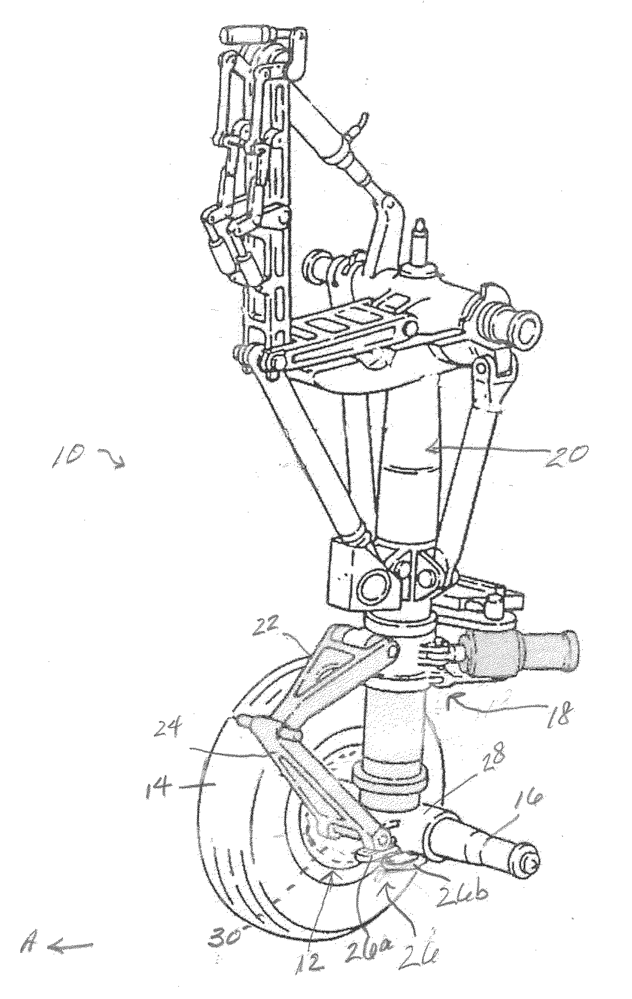
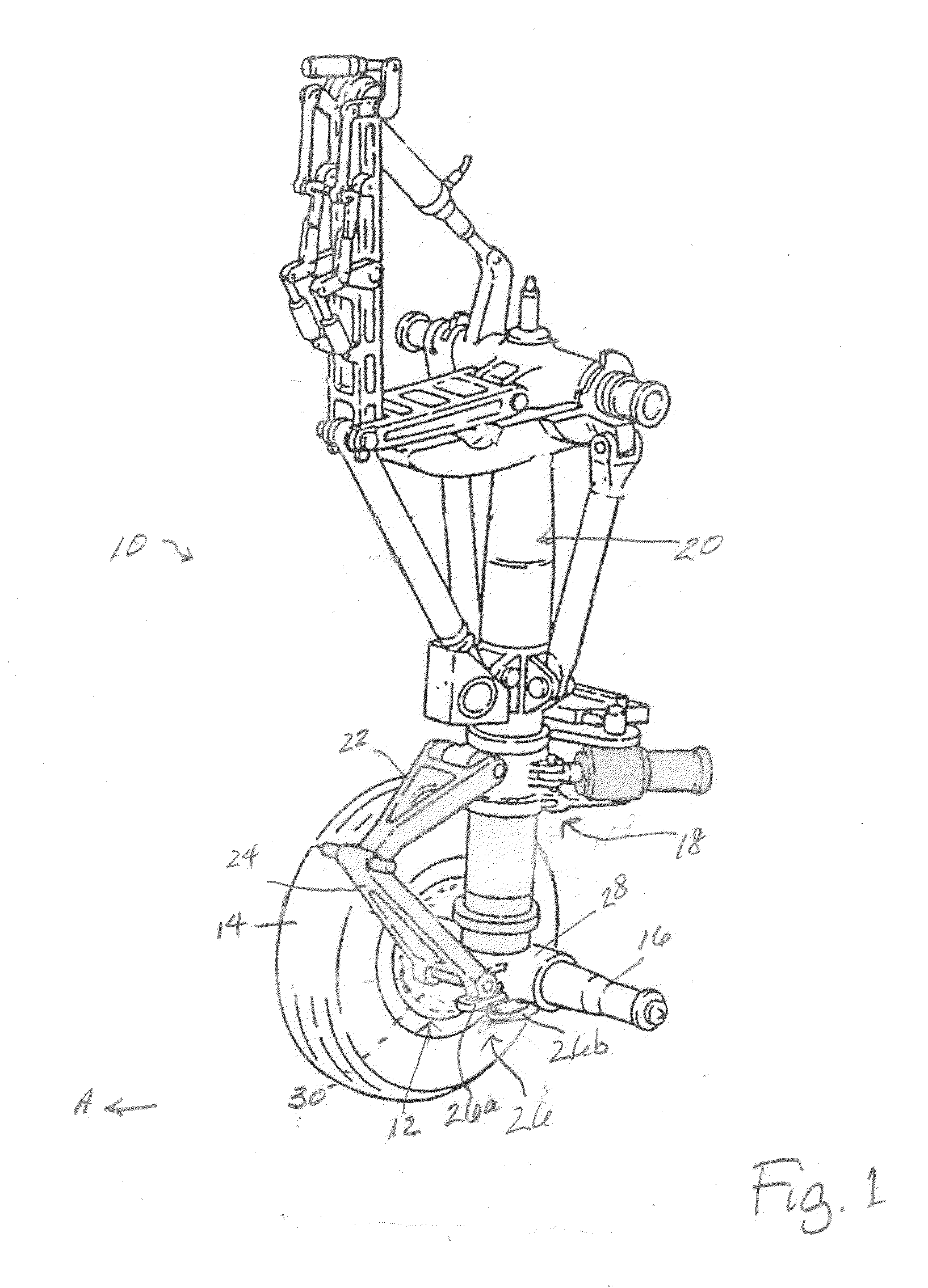
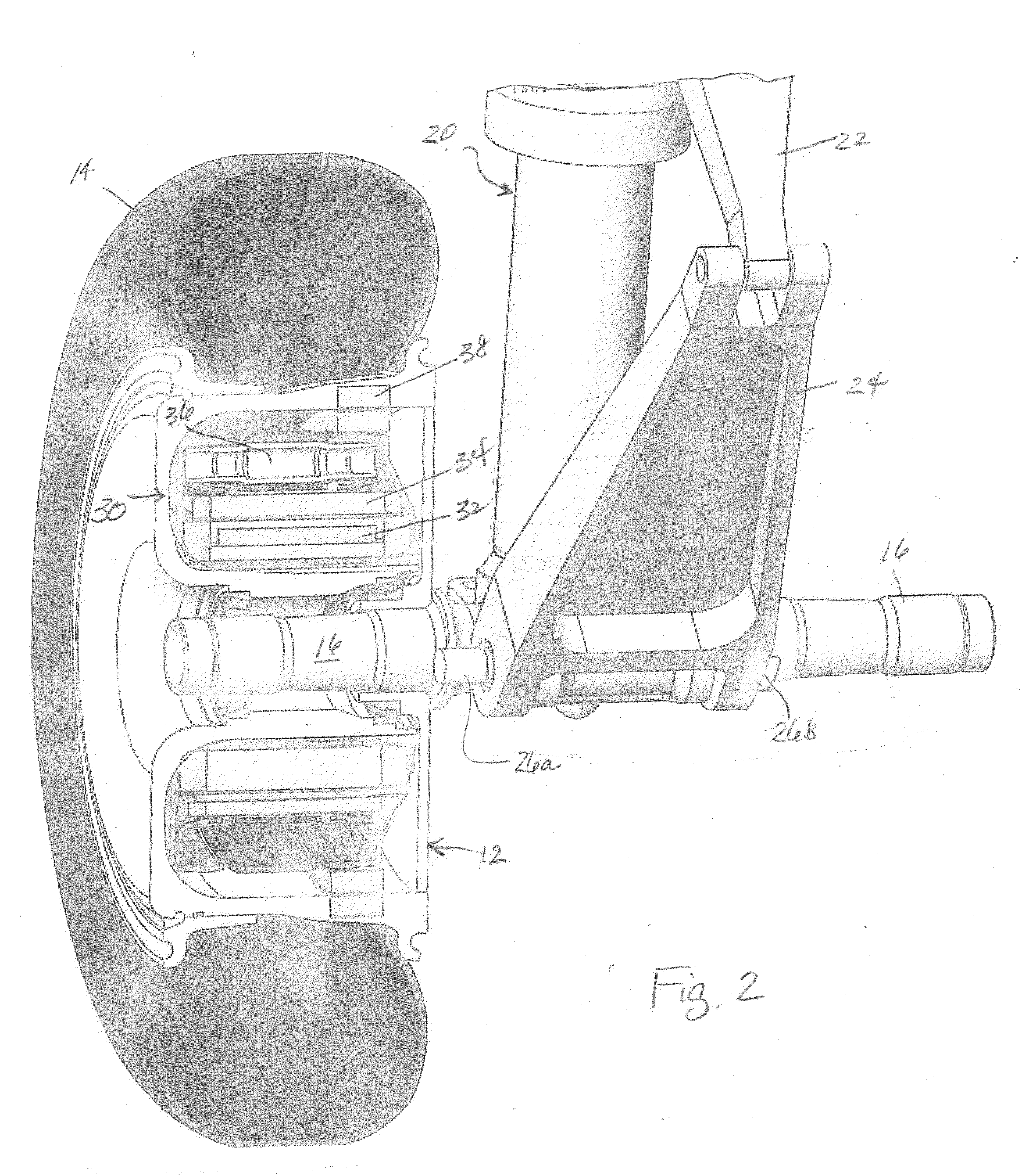
[0020]The benefits of being able to efficiently and safely move an aircraft during ground operations without reliance on the aircraft's main engines or external vehicles have long been recognized. Actually achieving these benefits, however, has proved challenging. Applicant's previously proposed aircraft landing gear wheel non-engine drive means have been demonstrated to effectively power landing gear wheels to move aircraft on the ground and, thus, can enable aircraft operators to achieve the advantages of autonomous engines-off taxi and / or ground movement. The present invention expands the advantages possible when aircraft can be efficiently retrofitted with and driven during ground operations by controllable onboard non-engine drive means independently of the aircraft's main engines and external tow vehicles using an aircraft's existing landing gear towing structures for transferring driving force. These advantages are achieved, in large part, by the design of an aircraft drive w...


PUM

PropertyMeasurementUnit
forceaaaaaaaaaa
torqueaaaaaaaaaa
drive forcesaaaaaaaaaa

Abstract

An efficient system and method are provided wherein aircraft may be retrofitted with non-engine drive means controllable to power landing gear wheels to move the aircraft autonomously during ground movement without engines or tow vehicles so that existing landing gear structures are employed to achieve force distribution and load transfer. Non-engine drive means capable of powering a landing gear wheel to move the aircraft during taxi are integrated into existing landing gear designs so that excess drive forces are transferred and distributed through previously evaluated and certificated landing gear structures, including tow fittings, determined to be capable of handling such forces, which eliminates changes to the landing gear and facilitates retrofit and certification. Engines-off taxi technology can be rapidly designed and developed to be retrofitted on existing aircraft nose and / or main landing gear and then efficiently certificated.

Description

PRIORITY CLAIM[0001]This application claims priority from International Patent Application No. PCT / US2013 / , filed 4 Dec. 2013, now withdrawn, the disclosure of which is fully incorporated herein by reference.TECHNICAL FIELD[0002]The present invention relates generally to the distribution of loads produced by operation of aircraft landing gear and specifically to a system and method for distributing loads and transferring forces in a nose landing gear in an aircraft equipped with a drive wheel powered by a non-engine drive means that moves the aircraft autonomously during ground travel.BACKGROUND OF THE INVENTION[0003]Aircraft landing gear are subjected to various loads and forces during operation of an aircraft. In addition to the obvious loads associated with landing any aircraft, landing gear are subjected to other forces during ground movement or taxi as the aircraft moves between landing and takeoff. Nose landing gear, which are the most common attachment location for the tugs o...

Claims


Application Information

Patent Timeline
Patent Type & Authority Applications(United States)
IPC IPC(8): B64C25/40B64F5/00B64C25/34
CPCB64C25/405B64F5/0081B64C25/34Y02T50/80Y10T29/49716
Inventor COX, ISAIAH W.PERKINS, SCOTT
Owner BOREALIS TECH LTD
Learn More