
Apparatus and method for repair of spinal cord injury

Inactive Publication Date: 2006-07-27
DYNAMED SYST
View PDF5 Cites 27 Cited by
  • Summary
  • Abstract
  • Description
  • Claims
  • Application Information

AI Technical Summary

Benefits of technology

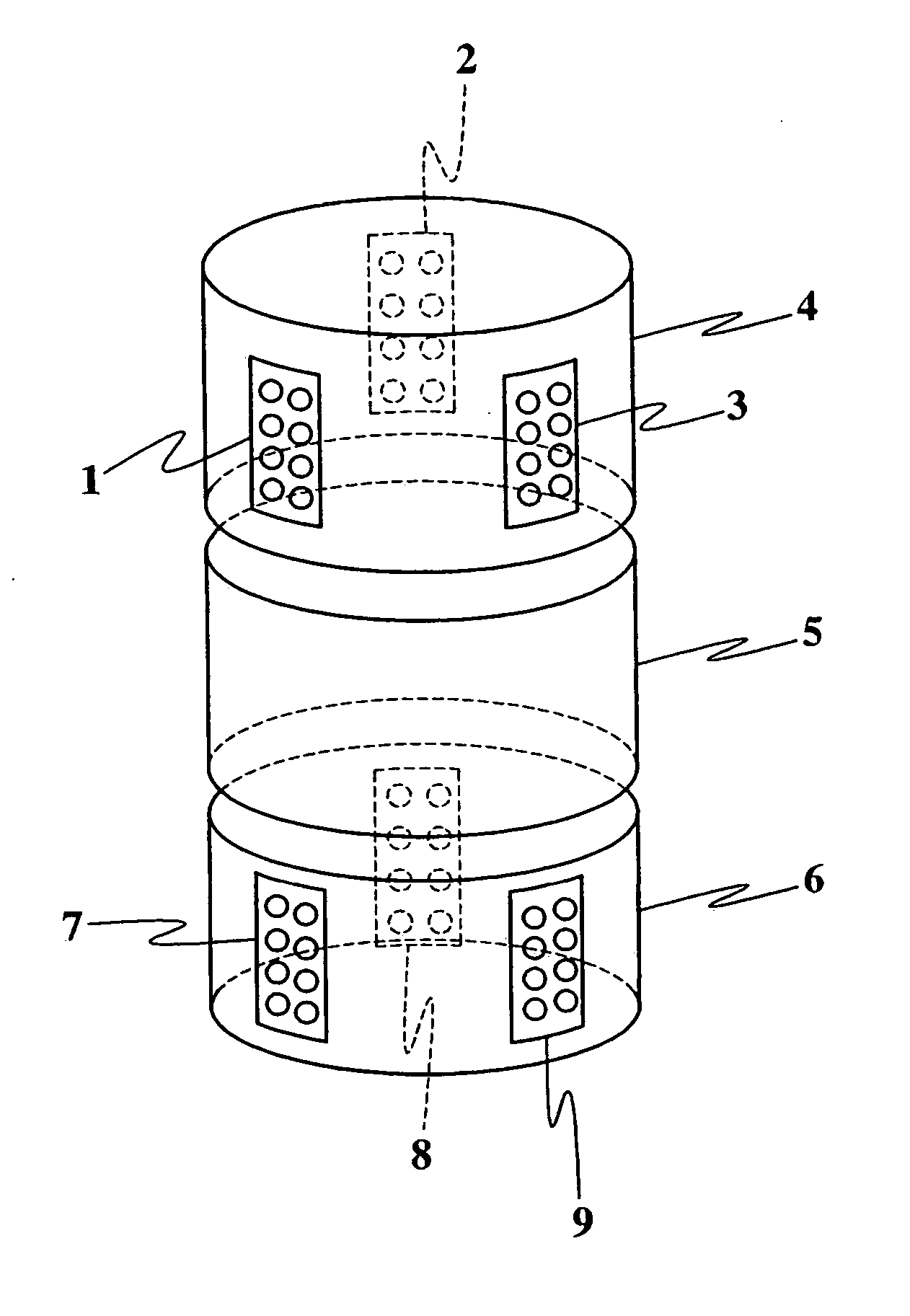
[0013] An aspect of the present invention includes at least two electrodes configured to be placed intravertebrally proximal to the site of spinal neurite injury and deliver direct current (DC) thereto. Each electrode includes an aggregate conductive electrode surface sufficiently large such that the current density from the electrode surface will induce neurite regeneration and repair without damaging the surrounding tissue. In a preferred embodiment, the aggregate electrode surface includes multiple conductive sub-surfaces. The conductive sub-surfaces are separated from each other by non-conducting septa to minimize the production of, and dissipate, any toxic product, such as free ionic protons, developed as the result of the delivery of electric current.
[0014] Another aspect of the present invention includes placing the electrodes of the present invention intravertebrally proximal to the site of spinal cord injury and applying direct current at a level sufficient to induce regeneration and repair of damaged spinal neurites but less than the current level at which tissue toxicity occurs. The current is applied for a duration sufficient to prevent significant die-back and achieve net growth.
[0016] In one aspect of the present invention, the direct current is applied for sufficient duration to prevent significant die-back, ensuring that forward-direction neurite regeneration and repair prevails over die-back.

Problems solved by technology

If the spinal cord is compressed, severed or contused, the physical or physiological integrity of neurites may be compromised, so that insufficient conduction of neuroelectric impulses can occur along the affected neurite's length.
Eventually, large populations of neurites, including their associated cell bodies, may die, causing massive loss in communication between the brain and the peripheral nerves, and resulting in varying degrees of paraplegia or quadriplegia.
Unfortunately, the density at which unbalanced direct current can be applied to nervous tissue is finite, with the upper limit being the level of toxicity where significant cell damage occurs.
However, extravertebral electrodes require significant amounts of power to produce effective field strengths within the damaged spinal cord.
As a result, more power is required to generate the requisite electric field to the injury site, potentially resulting in toxic effects to tissues in the immediate vicinity of the conductive electrode surface, such as muscle, nerves and blood vessels.
It is understood that regeneration and repair of spinal neurites is counterproductive if the muscles to be controlled or their associated blood vessels and nerves are damaged as a result.
Further, extravertebral placement of electrodes can result in situating the electrodes lateral to the site of the spinal cord injury, rather than in line therewith, resulting in less than optimal directional neurite guidance by the cathodal current.
Still further, extravertebral placement of electrodes affects the extent to which the electrical flux lines generated by the electrodes deviate from the ideal, which itself is a major determinant in the quality of the electrical field established in the spinal cord.
Extravertebral field application is rendered significantly less reliable and thus less efficacious as the result of the difficulty in predicting the effects of the different resistivity / conductivity parameters of the intervening tissues.

Method used


Image

  • Apparatus and method for repair of spinal cord injury
  • Apparatus and method for repair of spinal cord injury
  • Apparatus and method for repair of spinal cord injury

Examples


Embodiment Construction

[0022] The apparatus for stimulating regeneration and repair of damaged spinal neurons of the present invention includes at least two electrodes that are configured to be placed intravertebrally proximal the site of spinal neurite injury and deliver direct current thereto. The electrodes include an aggregate conductive electrode surface through which the direct current is delivered to the injury site. The aggregate conductive electrode surface is sufficiently large so that the density of the delivered direct current can induce neurite regeneration and repair without generating a significant amount of toxic product in surrounding tissues.

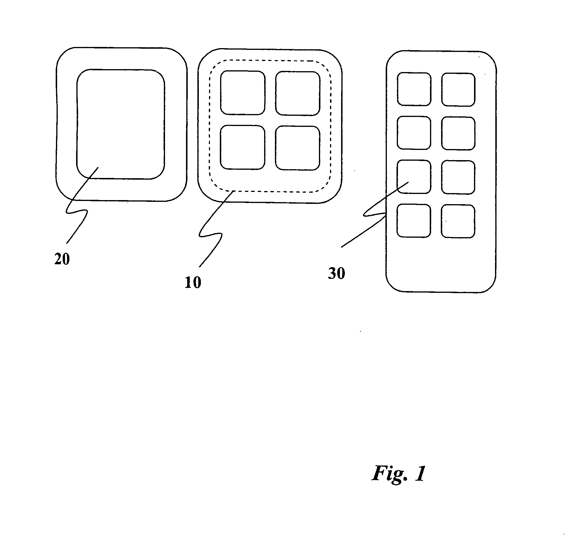
[0023] As shown in FIG. 1, the aggregate conductive electrode surface 10 may include a single conductive surface 20 or multiple conductive sub-surfaces 30. Where multiple conductive sub-surfaces 30 are used, the result is a flattening of the trans-surface current gradient, or “skin effect,” across each sub-surface. As shown in FIG. 2, the benefit is...


PUM


Abstract

An apparatus for stimulating regeneration and repair of damaged spinal nerves, comprising at least two electrodes placed intravertebrally near the site of spinal neurite injury and delivering direct current thereto. A method for stimulating regeneration and repair of damaged spinal nervous tissue, comprising placing electrodes intravertebrally near the site of spinal cord injury and applying direct current at a level sufficient to induce regeneration and repair of damaged spinal neurites but less than the current level at which tissue toxicity occurs.

Description

CROSS-REFERENCE TO RELATED PATENT APPLICATIONS [0001] This application is a continuation-in-part of U.S. patent application Ser. No. 10 / 292,414 filed Nov. 11, 2002, which claims priority from U.S. Provisional Patent Application Ser. No. 60 / 350,490. filed Nov. 13, 2001. All patents, patent applications, and references cited in this specification are incorporated by reference in their entirety.BACKGROUND OF THE INVENTION [0002] 1. Field of the Invention [0003] The present invention relates to an apparatus and method for repairing spinal cord injury, and specifically an apparatus and method for stimulating regeneration and repair of damaged spinal nervous tissue. [0004] 2. Discussion of the Related Art [0005] Spinal cord injury occurs when the normal function of axons or other neural fibers of the spinal cord (collectively: neurites) is interrupted, generally by mechanical forces. If the spinal cord is compressed, severed or contused, the physical or physiological integrity of neurites...

Claims


Application Information

Patent Timeline
IPC IPC(8): A61N1/18A61N1/05A61N1/20
CPCA61N1/205A61N1/326
Inventor FEMANO, PHILIP A.ZANAKIS, MICHAEL J.
Owner DYNAMED SYST
Learn More