Mixed powder for powder metallurgy and manufacturing method thereof
a technology of powder metallurgy and mixing powder, which is applied in the direction of metal-working apparatuses, grain treatment, transportation and packaging, etc., can solve the problems of increasing specific surface area, and achieve the effects of suppressing graphite segregation, excellent adhesion force, and excellent flowability
- Summary
- Abstract
- Description
- Claims
- Application Information
AI Technical Summary
Benefits of technology
Problems solved by technology
Method used
Image
Examples
example 1
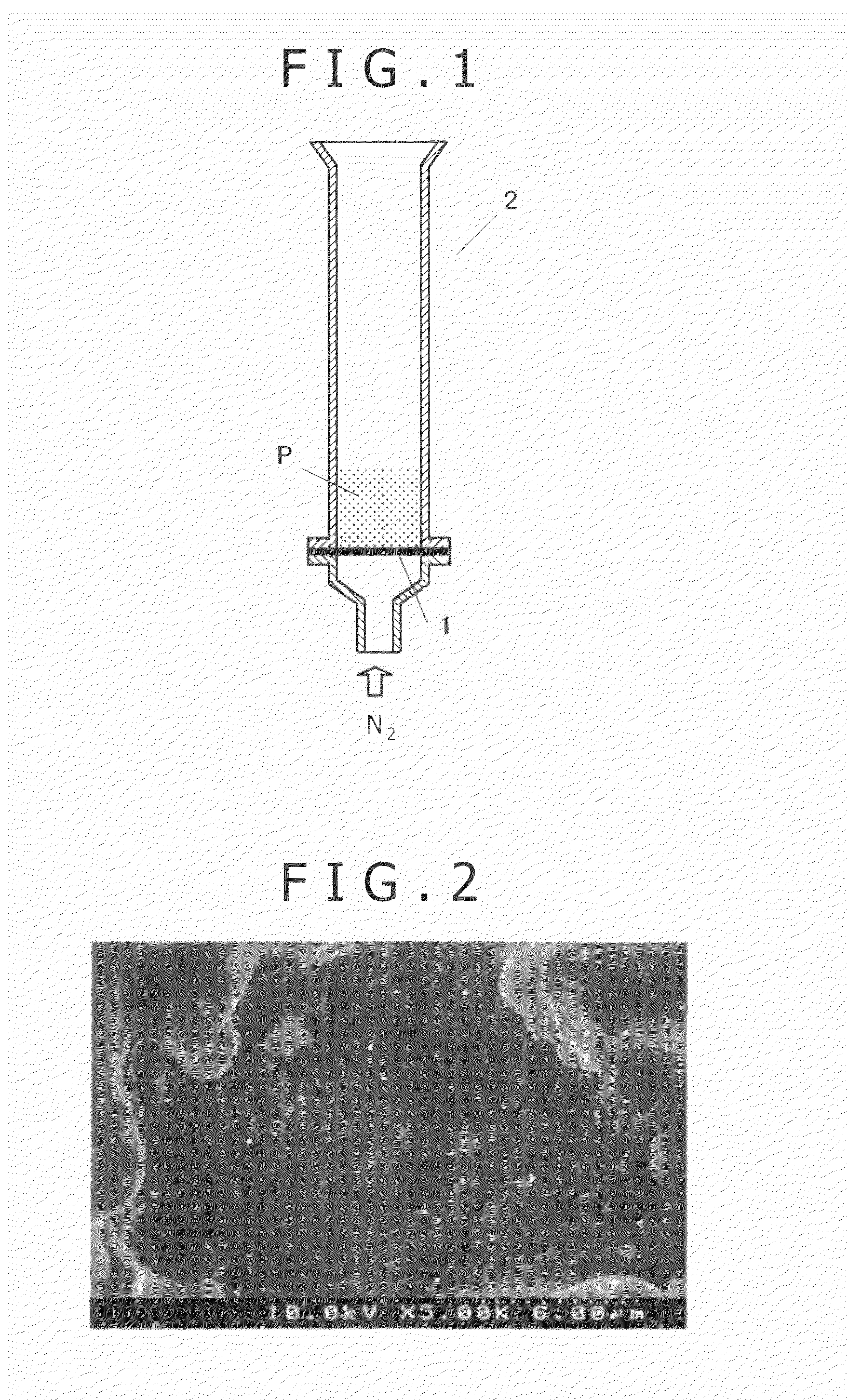
[0035]A commercially available natural graphite (manufactured by Nippon Graphite Ltd., JCPB, mean particle size 5.0 μm) was subjected to wet type bead mill crushing (solvent: water), then, was dried, and further was crushed by a dry type jet mill, resulting in a graphite with a mean particle size of 2.1 μm (the particle size of graphite was measured by a Microtrac 9300-X100). Per 100 parts by mass of an iron powder (manufactured by KOBE STEEL Ltd., Atmel 300M, particle side 180 μm or less, mean particle size 70 μm), 0.8 part by mass of the graphite was simultaneously charged into a high speed mixer without adding a binder or a lubricant, and without applying a heat thereto, and the mixture was mixed for 5 minutes, resulting in a mixed powder. The graphite scattering ratio of the resulting mixed powder was 1%. Further, the results obtained from observation under a SEM are shown in FIG. 2. FIG. 2 indicates that the fine graphite uniformly adheres to the surface of the iron powder.
[003...
example 2
[0037]Graphite powders obtained by adjusting a commercially available natural graphite (manufactured by Japan Graphite Co., Ltd., JCPB, mean particle size 5.0 μm) various particle sizes according to the methods described in Table 1 (wherein JCPB itself was used for Nos. 1 and 2 of Table 1), an iron powder (manufactured by KOBE STEEL Ltd., Atmel 300M, particle side 180 μm or less, mean particle size 70 μm), and a copper powder (manufactured by FUKUDA METAL FOIL & POWDER Co., Ltd., CE-20) were simultaneously added to their respective mixers shown in Table 1 in a ratio of copper powder: 2 parts by mass and graphite: 0.8 part by mass per 100 parts by mass of the iron powder, and each mixture was mixed, resulting in each mixed powder for graphite scattering ratio measurement. The particle size of each graphite was measured by the Microtrac 9300-X100 as with Example 1. Further, per 100 parts by mass of the mixed powder, 0.8 part by mass of an ethylenebisamide lubricant was mixed using eac...
example 3
[0041]Per 100 parts by mass of an iron powder (manufactured by KOBE STEEL Ltd., Atmel 300M, particle size 180 μm or less, mean particle size 70 μm), (i) the fine graphite used in Experiment No. 6 of Example 2, A15 carbon black manufactured by Degussa, and a commercially available natural graphite (manufactured by Japan Graphite Co., Ltd., JCPB, mean particle size: 5.0 μm) and, (ii) 2 parts by mass of a copper powder were simultaneously added to a high speed mixer with vanes, and the mixture was stirred for five minutes, resulting in a powder for measuring the graphite scattering ratio. Incidentally, the mixing ratios of the fine graphite, the carbon black, and the commercially available natural graphite (the ratios per 100 parts by mass of the iron powder) are as shown in Table 2. Further, 0.8 part by mass of an ethylenebisamide lubricant was mixed per 100 parts by mass of a graphite scattering ratio measuring mixed powder (stirred using a high speed mixer with vanes for 2 minutes),...
PUM
| Property | Measurement | Unit |
|---|---|---|
| mean particle size | aaaaa | aaaaa |
| particle size | aaaaa | aaaaa |
| mean particle size | aaaaa | aaaaa |
Abstract
Description
Claims
Application Information
 - R&D
- Intellectual Property
- Life Sciences
- Materials
- Tech Scout
- Unparalleled Data Quality
- Higher Quality Content
- 60% Fewer Hallucinations
Browse by: Latest US Patents, China's latest patents, Technical Efficacy Thesaurus, Application Domain, Technology Topic, Popular Technical Reports.
© 2025 PatSnap. All rights reserved.Legal|Privacy policy|Modern Slavery Act Transparency Statement|Sitemap|About US| Contact US: help@patsnap.com

