
Method and plant for removing acid compounds from gaseous effluents of different origins

a gaseous effluent and acid compound technology, which is applied in the direction of sulfur compounds, hydrogen sulfides, separation processes, etc., can solve the problems of high flow rate of solution to be regenerated, direct impact of energy consumption required for regeneration, and energy consumption of amine absorbent solutions commonly used today, so as to reduce the investment cost of co2 capture and energy needs, reduce the investment cost of acid compound removal plant and energy needs, and reduce the effect of energy consumption

Inactive Publication Date: 2015-05-21
INST FR DU PETROLE
View PDF0 Cites 3 Cited by
  • Summary
  • Abstract
  • Description
  • Claims
  • Application Information

AI Technical Summary

Benefits of technology

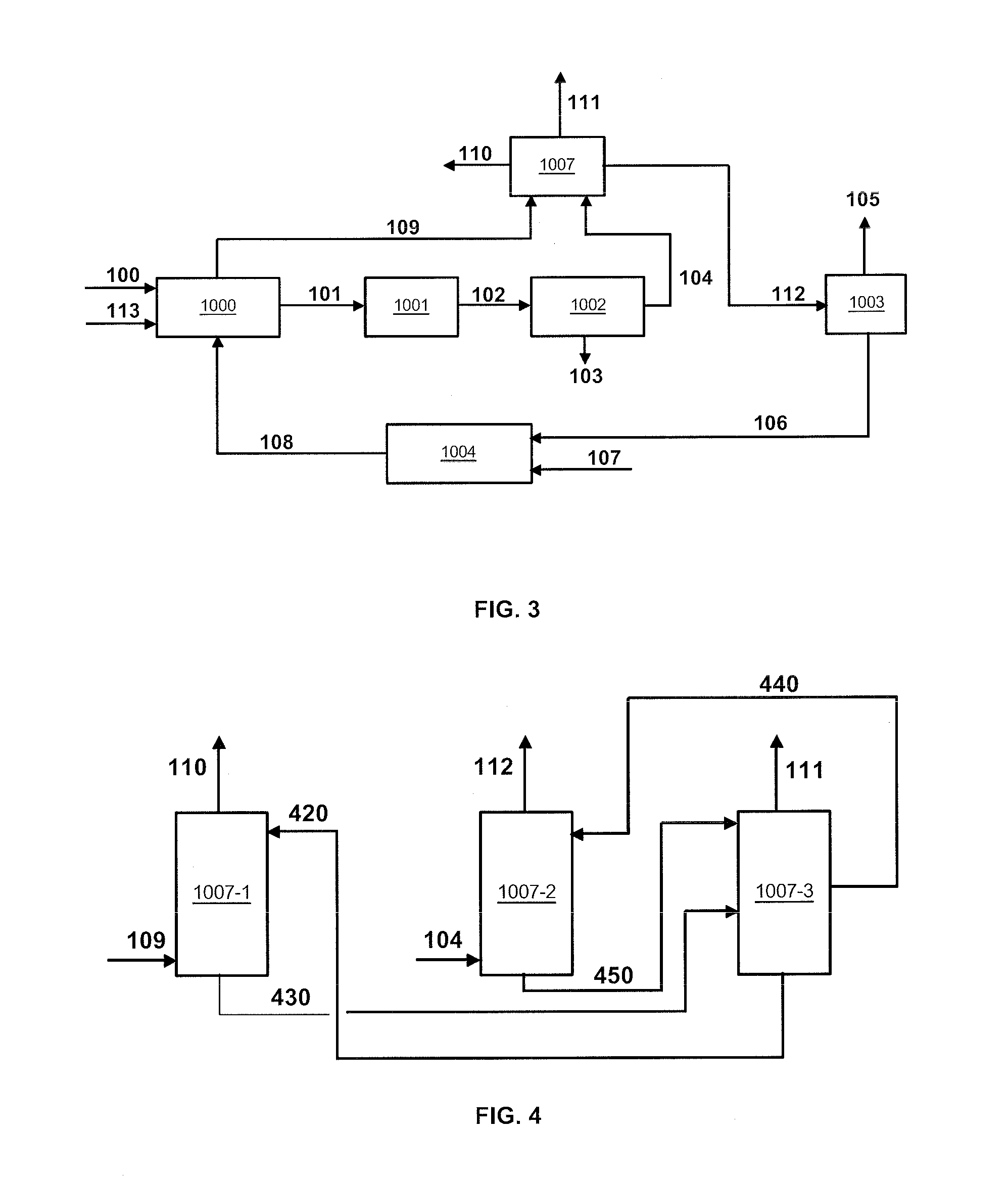
The present invention is aimed at providing a method for efficiently capturing CO2 formed during industrial hydrogen production, using an amine-based absorbent solution. This method should reduce the investment cost and energy requirements for CO2 capture and absorbent solution regeneration. Additionally, the invention also aims to remove acid compounds from gaseous effluents of different origins using an amine-based absorbent solution, with the same limitations mentioned earlier. The position of the delivery line for the first solution enriched in acid compounds is determined based on the loading rate and temperature to minimize heat consumption during regeneration of the absorbent solution.

Problems solved by technology

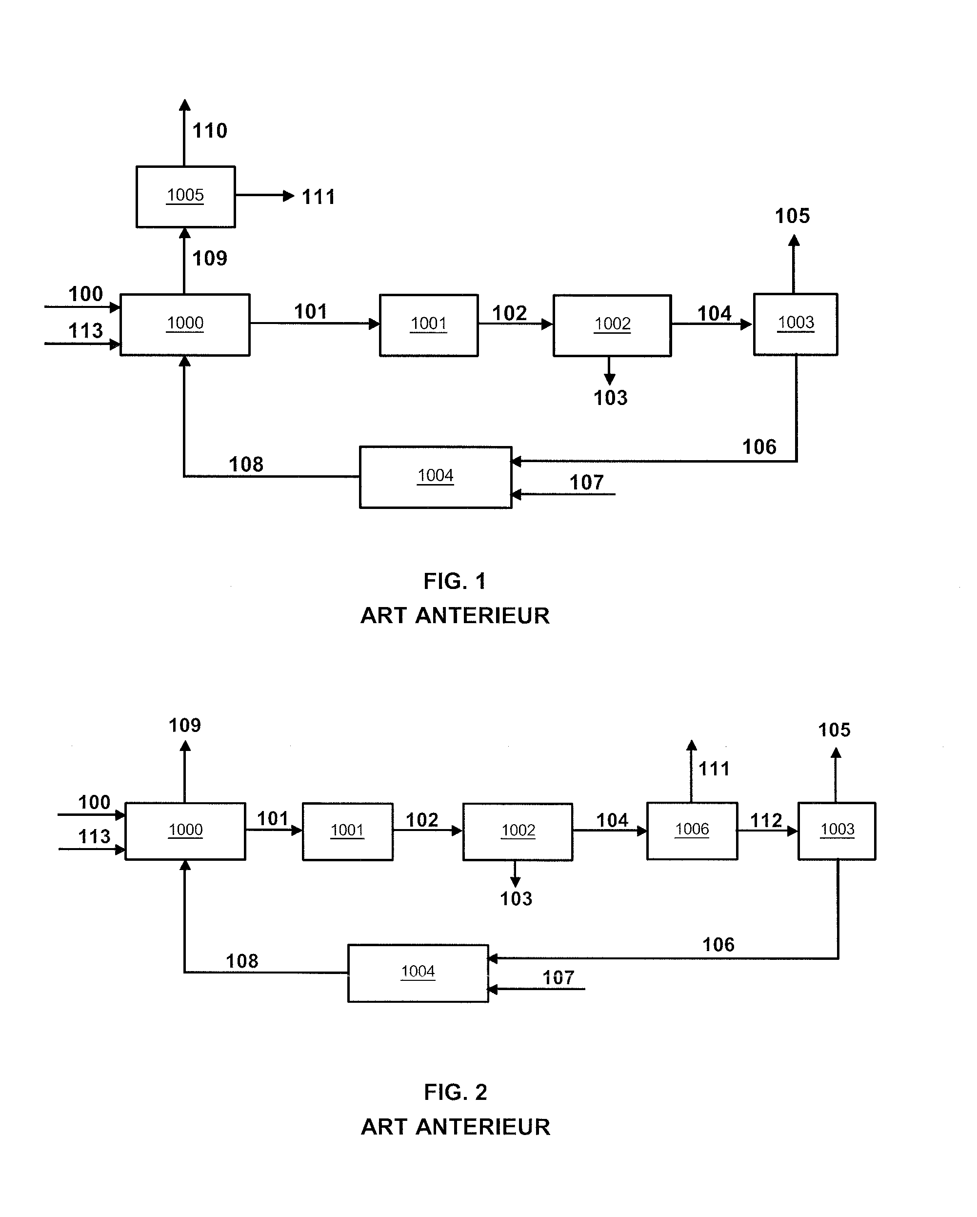
A major drawback of CO2 capture according to FIG. 1 lies in the fact that a significant amount of CO2 is captured on combustion fumes at atmospheric pressure, which requires using high absorbent solution flow rates, and therefore high flow rates of solution to be regenerated.
Now, a main limitation of the methods based on the amine absorbent solutions commonly used today is the energy consumption necessary for regeneration of the solution.
Thus, the energy consumption required for regeneration is directly impacted by high flow rates of solution to be regenerated, as well as the size of the columns and the associated investment costs.
A major drawback of this solution is that only part of the CO2 produced during the hydrogen production process is captured: the part resulting from the reforming and CO conversion reactions, but not the part resulting from combustion in the furnace.

Method used


Image

  • Method and plant for removing acid compounds from gaseous effluents of different origins
  • Method and plant for removing acid compounds from gaseous effluents of different origins
  • Method and plant for removing acid compounds from gaseous effluents of different origins

Examples


examples

[0108]The example relates to the deacidizing method according to FIGS. 3 and 4. The compositions, flow rates, temperature and pressure of gaseous effluents 104 and 109 to be deacidized are given in Table 1 hereafter.

TABLE 1Effluent 109Effluent 104(combustion gas)(syngas)Pressure (bar a)1.0226.7Temperature (° C.)172.676Flow rate (kmol / h)1364020465Vapour fraction (%)100100Molar fraction (%)Methane—4.3Hydrogen—74.3CO—0.8CO214.218.8O26.20N265.50.2H2O13.31.6Other organic—>ppm by moleconstituentsAr0.8

[0109]According to FIGS. 1 and 2 representing the prior art, effluents 104 and 109 can be treated by two distinct amine treating units. These treating units however need to respect a different CO2 removal rate for each gaseous effluent. For gas 104 representing the syngas, the CO2 removal rate has to be at least 98.5%. For effluent 109 representing the combustion gas, the CO2 removal rate has to be at least 90%.

[0110]For example, effluents 104 and 109 are treated with an absorbent solution co...


PUM

PropertyMeasurementUnit
Pressureaaaaaaaaaa
Pressureaaaaaaaaaa
Pressureaaaaaaaaaa

Abstract

The invention relates to a method and a plant for removing the acid compounds contained in two gaseous effluents of different origins, comprising using a single amine-based absorbent solution circulating between a first absorber and a regenerator, and a second absorber and the same regenerator. The present invention advantageously applies for example to CO2 capture within a single plant intended for capture of the gaseous effluents produced upon hydrogen production through steam reforming of a gaseous hydrocarbon feed, such as combustion fumes and syngas.

Description

FIELD OF THE INVENTION[0001]The present invention relates to the sphere of deacidizing gaseous effluents comprising acid compounds such as carbon dioxide (CO2) and hydrogen sulfide (H2S) using an amine-based absorbent solution. The present invention applies in particular to CO2 capture upon hydrogen production through steam reforming of a gaseous hydrocarbon feed and to H2S removal from gaseous effluents produced upon hydrotreatment of liquid hydrocarbon feeds.General Context[0002]Controlling greenhouse gas emissions, notably CO2 emissions, is becoming an increasingly strong requirement for all economic sectors, in particular those concerning energy production. Industrial hydrogen production, generally based on natural gas steam reforming, is part of these sectors that emit large amounts of CO2.[0003]One of the various possible ways of controlling CO2 emissions is CO2 capture through absorption methods using an aqueous amine solution, for example alkanolamines such as monoethanolami...

Claims


Application Information

Patent Timeline
IPC IPC(8): B01D53/14B01D53/62B01D53/96B01D53/18
CPCB01D53/1456B01D53/18B01D53/1425B01D2252/204B01D53/62B01D53/96B01D53/1468B01D53/1475B01D2252/20484B01D2252/20489B01D2256/16B01D2256/24B01D2258/0283Y02A50/20Y02C20/40
Inventor GIROUDIERE, FABRICEGOMEZ, ADRIEN
Owner INST FR DU PETROLE
Learn More