Conductive porous layer for battery, and manufacturing method for same
- Summary
- Abstract
- Description
- Claims
- Application Information
AI Technical Summary
Benefits of technology
Problems solved by technology
Method used
Image


Examples
example 1
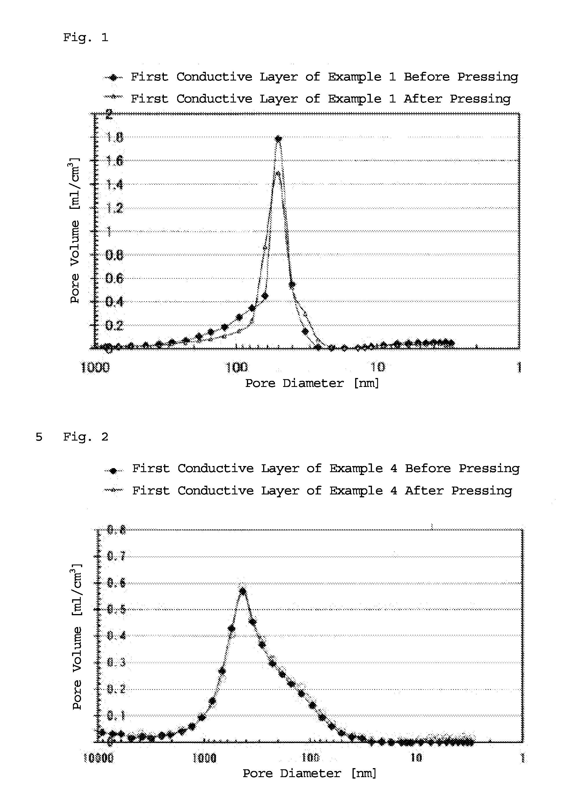
(i) First Conductive Layer
[0161]Polymer (1) was added to methyl ethyl ketone, and the mixture was stirred using a stirrer (media rotation speed: 300 rpm) at 80° C. for 60 minutes, thereby obtaining a PVDF solution having a solids content (polymer (1)) of 10 wt % in which polymer (1) was dissolved in the methyl ethyl ketone. Conductive carbon particles (100 parts by weight), polymer (4) (50 parts by weight), the prepared PVDF solution having a solids content of 10 wt % (500 parts by weight, solids content: 50 parts by weight), polymer (3) (100 parts by weight, solids content: 70 parts by weight), and methyl ethyl ketone (1000 parts by weight) were subjected to media dispersion to prepare a first conductive layer-forming paste composition. The first conductive layer-forming paste composition was applied to a polyethylene terephthalate (PET) film including a release layer to a thickness of about 50 μm using an applicator. Regarding the viscosity of the paste composition, the shear visc...
example 2
(i) First Conductive Layer
[0164]Two first conductive layers (the Tg of the polymer contained in the conductive layer was 250° C.) were produced in the same manner as in Example 1 (i).
(ii) Second Conductive Layer
[0165]A second conductive layer (the Tg of the polymer contained in the layer was −60° C.) was produced in the same manner as in Example 1 (ii).
(iii) Conductive Porous Layer
[0166]The first conductive layer and the second conductive layer were each individually detached from the PET film including the release layer, and the surface of the first conductive layer having the polymers (polymers (1), (3), and (4)) with a higher density was disposed adjacent to the surface of the second conductive layer having the polymer (polymer (2)) with a lower density. Subsequently, the surface of the other first conductive layer having the polymers with a lower density was disposed adjacent to the surface of the second conductive layer having the polymer with a higher density. Hot-pressing was...
example 3
(i) First Conductive Layer
[0167]A first conductive layer (the Tg of the polymer contained in the layer was 250° C.) was produced in the same manner as in Example 1 (i).
(ii) Second Conductive Layer
[0168]A second conductive layer (the Tg of the polymer contained in the layer was −60° C.) was produced in the same manner as in Example 1 (ii).
(iii) Conductive Porous Layer
[0169]With the first conductive layer and the second conductive layer still attached to the PET film including the release layer, the surface of the first conductive layer having the polymers (polymers (1), (3), and (4)) with a lower density was disposed adjacent to the surface of the second conductive layer having the polymer (polymer (2)) with a lower density. Hot-pressing was then performed at a pressing temperature of 60° C. and a pressing pressure of 20 kN, for a pressing time of 60 seconds. The PET film including the release layer was then detached from each layer to produce the conductive porous layer of Example 3...
PUM
| Property | Measurement | Unit |
|---|---|---|
| Temperature | aaaaa | aaaaa |
| Glass transition temperature | aaaaa | aaaaa |
| Glass transition temperature | aaaaa | aaaaa |
Abstract
Description
Claims
Application Information
 - R&D
- Intellectual Property
- Life Sciences
- Materials
- Tech Scout
- Unparalleled Data Quality
- Higher Quality Content
- 60% Fewer Hallucinations
Browse by: Latest US Patents, China's latest patents, Technical Efficacy Thesaurus, Application Domain, Technology Topic, Popular Technical Reports.
© 2025 PatSnap. All rights reserved.Legal|Privacy policy|Modern Slavery Act Transparency Statement|Sitemap|About US| Contact US: help@patsnap.com