
Multielectrode array and method of fabrication

a technology of multi-electrode arrays and fabrication methods, applied in the field of multi-electrode arrays, can solve the problems of limited bonding technique, low adhesion strength, and short lifespan, and achieve the effects of enhancing neural growth or peripheral nerves, reducing the immune response, and reducing the risk of fractur

Active Publication Date: 2015-05-07
RGT UNIV OF CALIFORNIA
View PDF7 Cites 5 Cited by
  • Summary
  • Abstract
  • Description
  • Claims
  • Application Information

AI Technical Summary

Benefits of technology

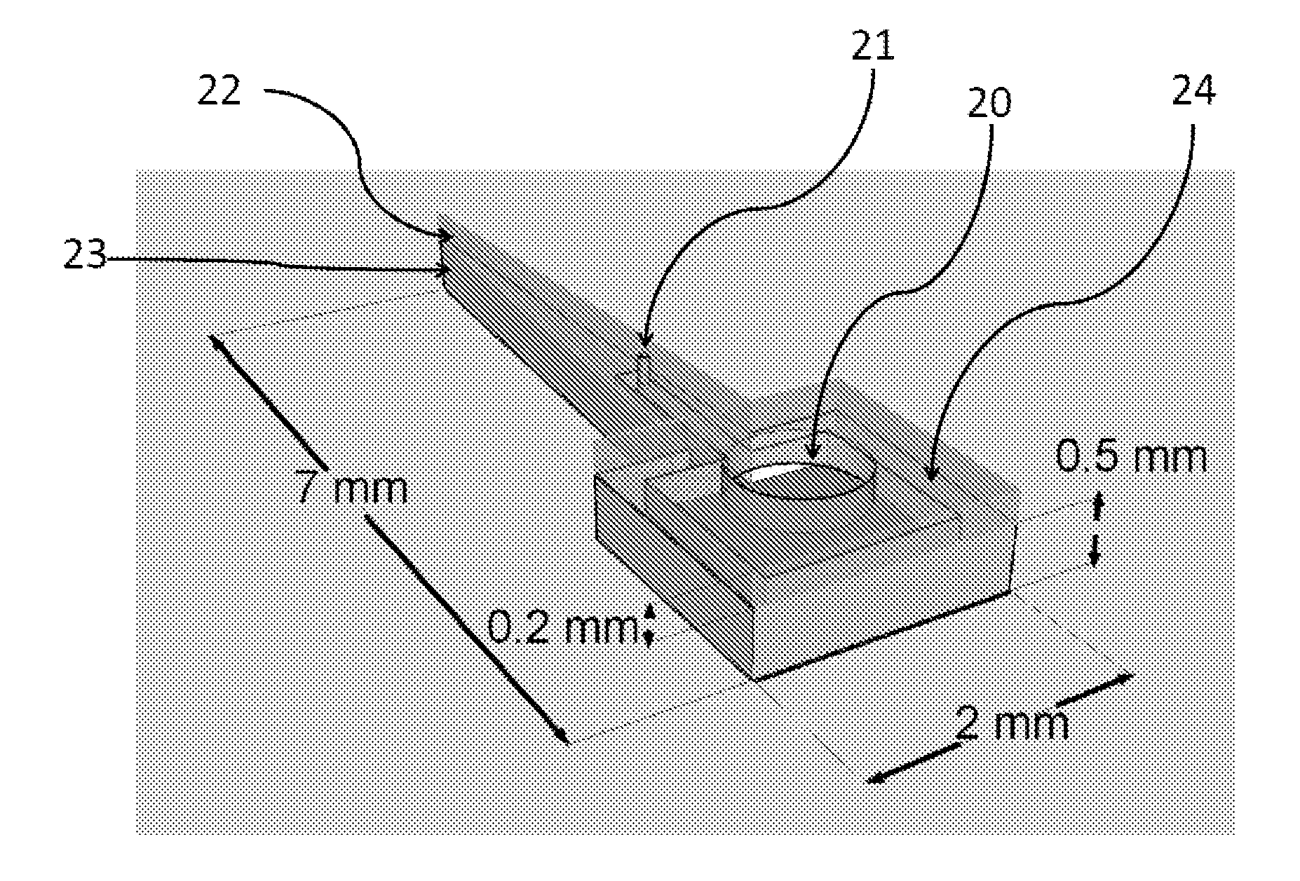
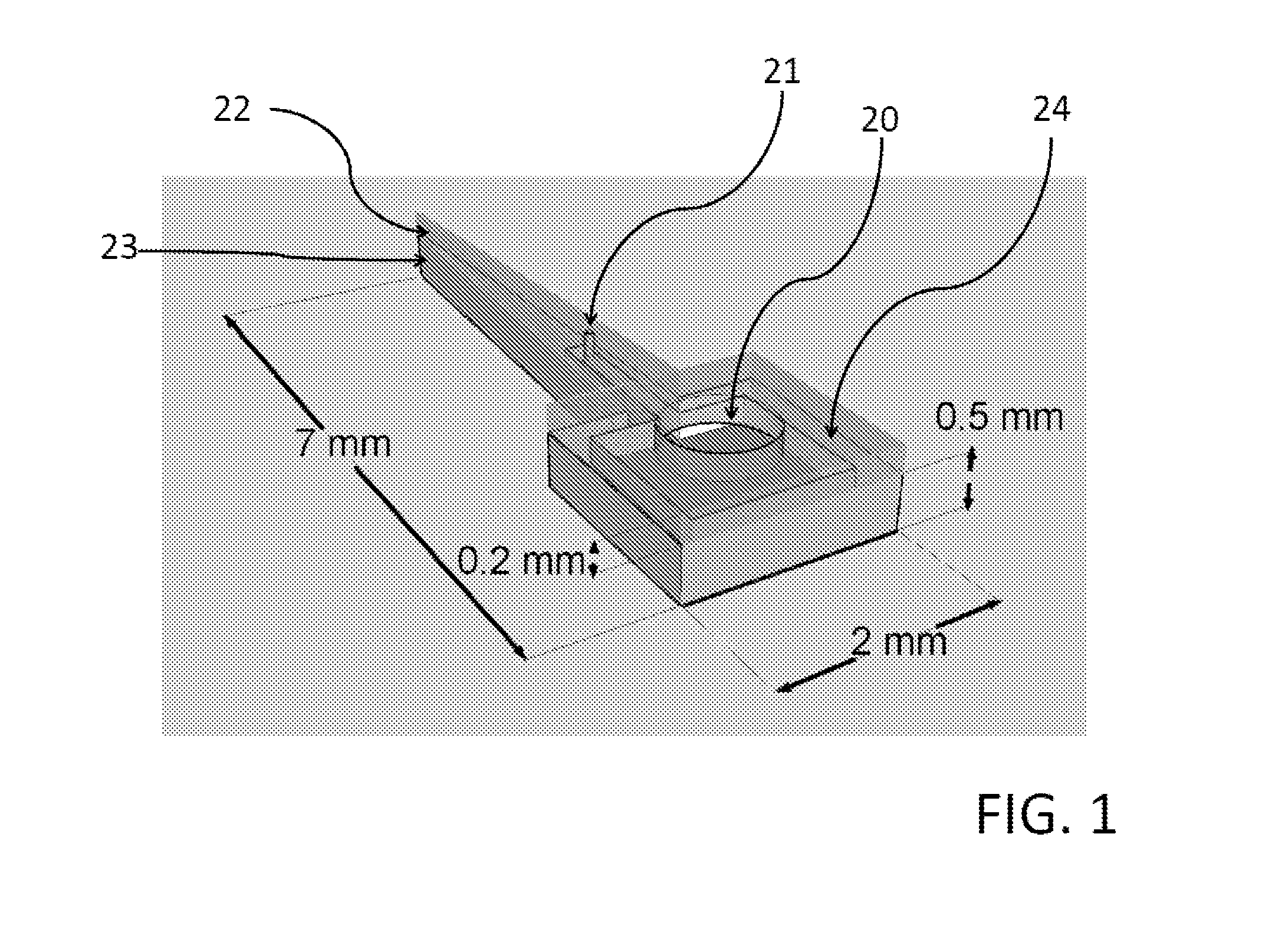
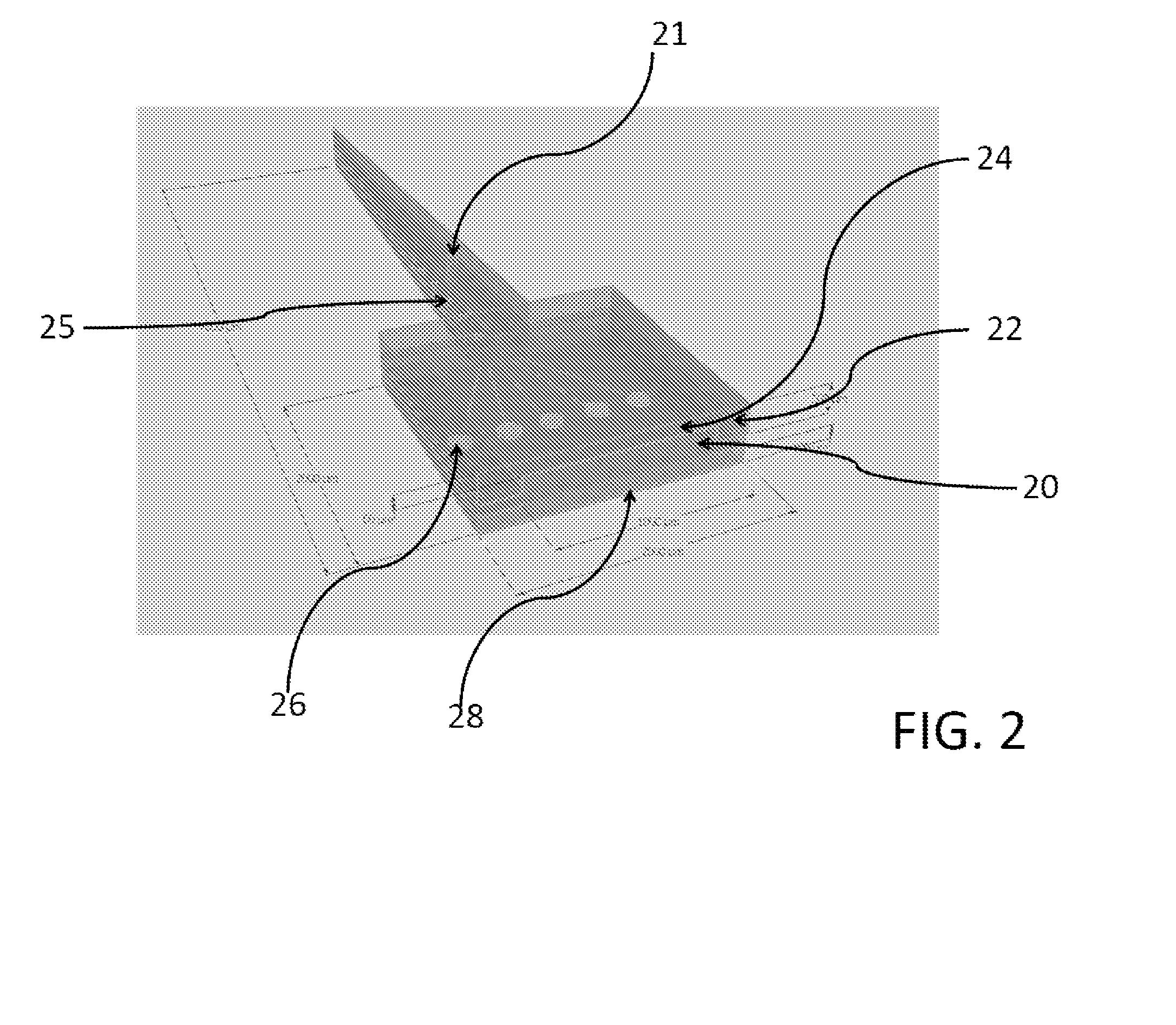
The present invention is a multielectrode with fluidic delivery capability that can be implanted into the body to enhance neural growth and reduce the immune response. The invention includes a microelectrode with a fluid channel in a negative photoresist, such asSU- 8, embedded within it. The fluidic channel can be partially sealed and the electrode sites can be manufactured using novel methods. The dimensions of the probes are defined by current material and equipment limitations, and further scaling can become apparent from the details provided herein.

Problems solved by technology

Although microelectrodes have demonstrated success, their short lifespans are a barrier to clinical practicality.
The limitation of bonding technique occurs from low adhesion strength, poor alignment.
Fluidic channels fabricated with sacrificial layers and dielectric sealing methods are limited by deliverable volume.
The challenge in multielectrode fabrication efforts today is developing processes that allows for scalability, reproducibility, and precision dimension control.

Method used


Image

  • Multielectrode array and method of fabrication
  • Multielectrode array and method of fabrication
  • Multielectrode array and method of fabrication

Examples


example 1

[0059]Generally

[0060]A silicon based microelectrode with an embedded fluidic channel is developed to deliver growth factors and drugs that would mitigate the cellular responses that have limited the chronic implementation of current multielectrode arrays. Two types of silicon based microelectrodes were developed, one with the fluidic channel etched into the silicon, and SU-8 was used to make the roof. The second consist of a silicon electrode with a SU-8 fluidic channel.

[0061]A third microelectrode that is made completely out of SU-8 (Shank, and fluidic channel) was constructed. In addition to delivering drugs and growth factors, a flexible SU-8 based neural probe with fluidic and electrical capabilities was developed to further extend the longevity of neural electrodes by reducing the tissue / electrode mechanical mismatch of traditional silicon based neural electrodes. In addition to extending the life of probe, the SU-8 material is a biocompatablie insulator with the potential for ...

example 2

[0064]Fabrication

[0065]Three preferred embodiments of the device are presented. In the first embodiment, a silicon microelectrode consist of at least one electrode site on one surface, on the opposite surface, a silicon channel is etched using microelectromechanical system technology, and the etched channel is sealed to form the fluidic channel in the microelectrode. In the second embodiment, a silicon microelectrode consist of at least one electrode site on one surface, on the opposite side, consist of fluidic channel that was photolithogoraphically fabricated. In third embodiment, the microelectrode consist entirely out of SU-8 and consist of a Fluidic channel and at least one electrode site. In these embodiments the electrode materials can easily change by those skilled in the art. The dimensions and manufacturing specification specified in the present invention are for illustration of the preferred embodiment, and can easily be changed by those skilled in the art, and with new m...


PUM

PropertyMeasurementUnit
wavelengthsaaaaaaaaaa
wavelengthaaaaaaaaaa

Abstract

A multielectrode array with a fluidic channel and its method of fabrication are presented here. In accordance with various embodiments, the present invention allows for scalability, reproducibility, and precision dimension control by utilizing a lithography dependent process. In one embodiment, the present invention provides for a microelectrode that is a neural implant, with the microelectrode configured for connection to a fluidic channel. In another embodiment, the fluidic channel may deliver growth factors and / or drugs.

Description

CROSS-REFERENCE TO RELATED APPLICATIONS[0001]The present application claims the benefit of priority under 35 U.S.C. §119(e) of provisional application Ser. No. 61 / 900,260 filed Nov. 5, 2013, the contents of which are hereby incorporated by reference.FIELD OF USE[0002]The present invention relates to the technical field of multielectrodes. More particularly, the present invention is in the technical field of neural implants. More particularly, the present invention is in the technical field of implantable microelectrodes for reading physiological signals within a body.BACKGROUND[0003]All publications herein are incorporated by reference to the same extent as if each individual publication or patent application was specifically and individually indicated to be incorporated by reference. The following description includes information that may be useful in understanding the present invention. It is not an admission that any of the information provided herein is prior art or relevant to ...

Claims


Application Information

Patent Timeline
Patent Type & Authority Applications(United States)
IPC IPC(8): A61B5/00G03F7/20A61B5/04
CPCA61B5/686G03F7/2002A61B5/04001A61B2562/028A61B2562/12A61B5/24G03F7/038A61N1/05
Inventor PEMBA, DHONAMTANG, WILLIAM C.
Owner RGT UNIV OF CALIFORNIA
Learn More