
Method for injection molding end muckets to a previously molded vehicle panel and prior to installation of a separately extruded and elongated compression seal

a technology of injection molding and vehicle panels, which is applied in the direction of transportation and packaging, manufacturing tools, and other domestic objects, can solve the problems of bulk transportation and storage requirements, and achieve the effect of improving upon inefficiencies

Inactive Publication Date: 2015-05-07
U S FARATHANE CORP
View PDF5 Cites 7 Cited by
  • Summary
  • Abstract
  • Description
  • Claims
  • Application Information

AI Technical Summary

Benefits of technology

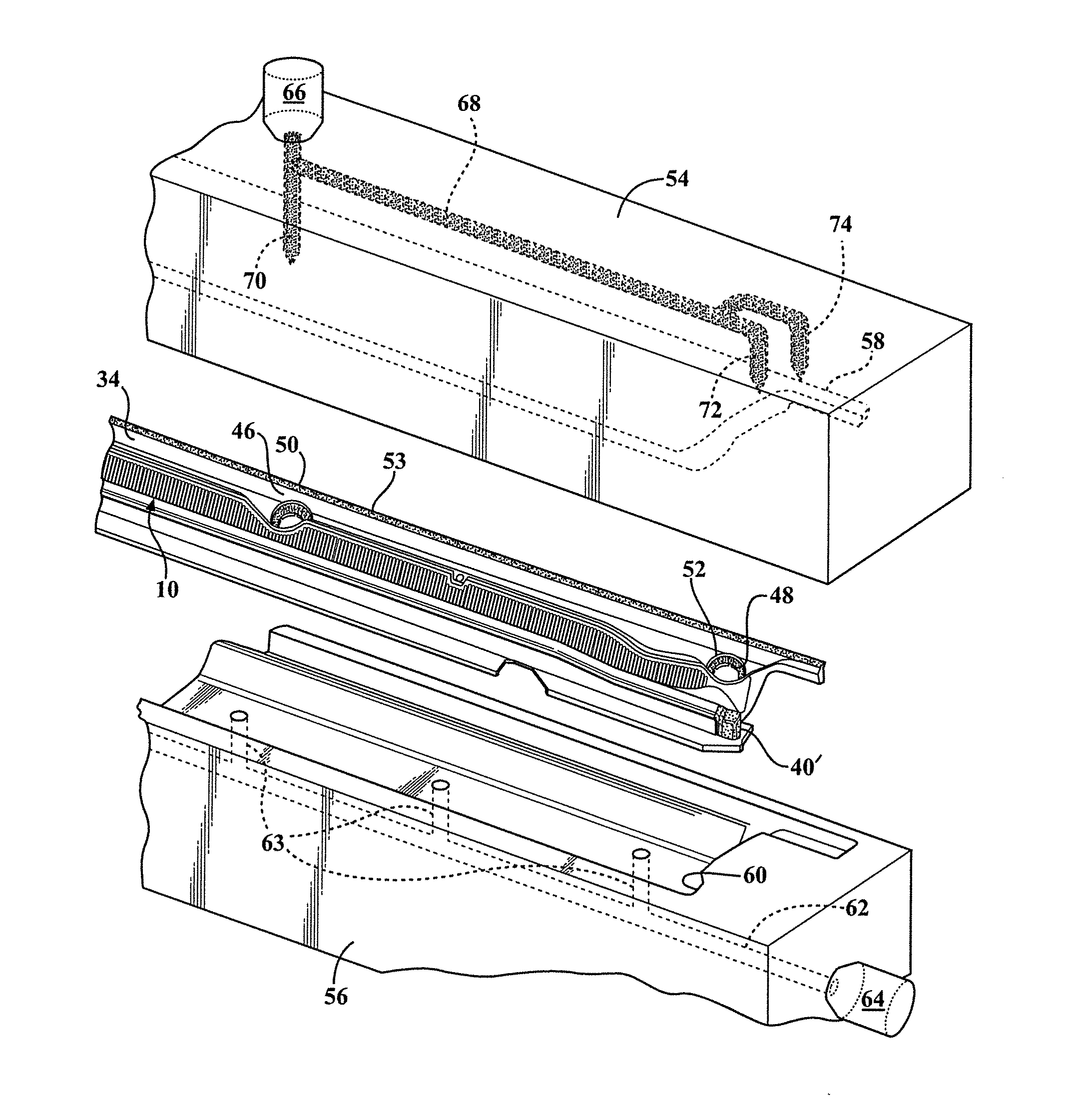
This patent describes a method for molding two parts called end muckets during a second stage injection molding process. These parts are used to attach seals to a vehicle panel. This method improves efficiency by combining the molding of the two parts into the panel, instead of separate stages for each part. The panel also has a channel that helps hold the seal in place. This saves material and ensures a strong connection between the panel and the vehicle's fenders.

Problems solved by technology

Disadvantages associated with the prior art fabrication and attachment of the end muckets include necessitating bulk transport and storage requirements of the muckets, and further requiring that they be successively pre-placed in correct aligning fashion, along with the previously created and applied extruded seal secured to the body panel / cowl, and prior to the end muckets being mechanically or adhesively secured such as to the ends of the extruded seal component.

Method used


Image

  • Method for injection molding end muckets to a previously molded vehicle panel and prior to installation of a separately extruded and elongated compression seal
  • Method for injection molding end muckets to a previously molded vehicle panel and prior to installation of a separately extruded and elongated compression seal
  • Method for injection molding end muckets to a previously molded vehicle panel and prior to installation of a separately extruded and elongated compression seal

Examples


Embodiment Construction

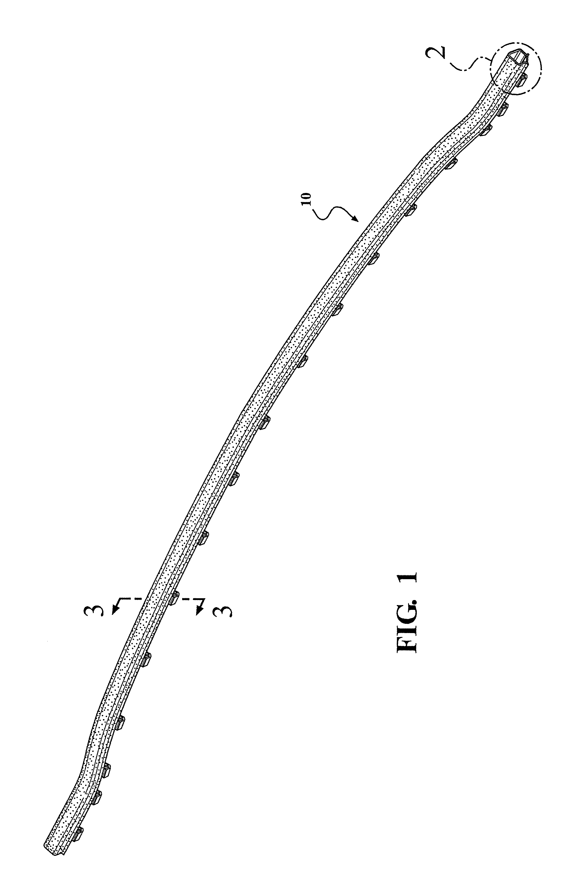
[0028]As previously described, the present invention discloses a method for injection molding a pair of seal supporting end muckets to a previously molded vehicle panel. The seal, without limitation, can include any construction and, in particular, can be a coextruded or tri-extruded bulb seal which is constructed of at least one softer and one harder polymer material for various in-vehicle applications. Such seals can be integrated along extending edge interfaces associated with the cowl to hood, rocker seal, grill seal, rear trunk and deck lid seals, lift gate seal, etc. Among other advantages, the seal eliminates the need for a secondary molded attachment pin, as it is integrated into the part.

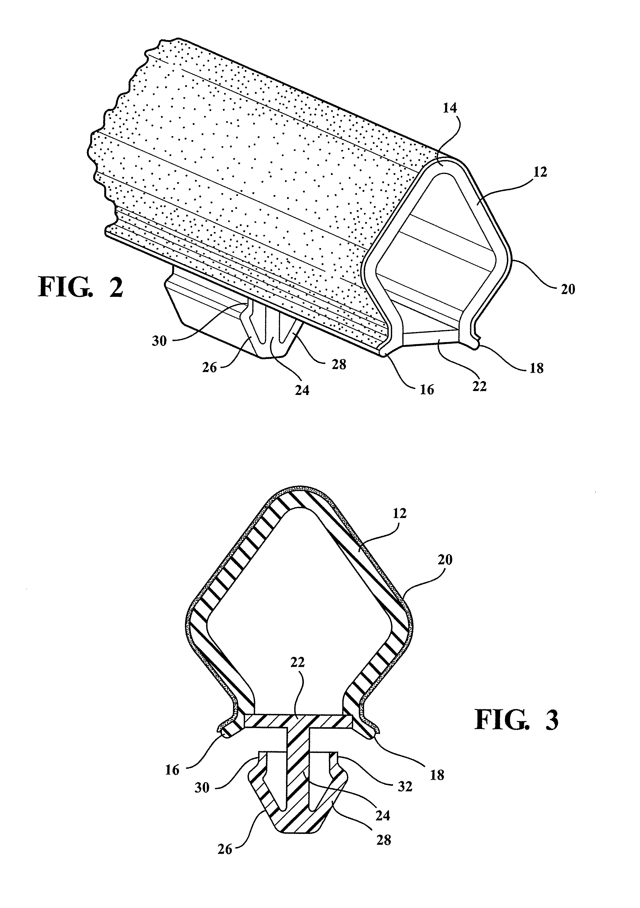
[0029]One non-limiting depicted variant of cowl to hood seal provides a tri-extruded article, including a base attaching material exhibiting a more rigid filled or unfilled polypropylene, a polygonal and interiorly hollowed softer thermoplastic olefin, thermal plastic vulcanite, ethylene pr...


PUM

PropertyMeasurementUnit
widthaaaaaaaaaa
frictional coefficientaaaaaaaaaa
transparencyaaaaaaaaaa

Abstract

A method for injection molding a pair of end muckets to a previously injection molded panel and prior to attaching a separately formed seal. The method includes the step of initially forming a vehicle panel from a first material in a closed cavity, following which a second stage injection molding process forms a pair of end muckets onto the panel. The separately formed seal exhibits an elongated profile and is inter-fitted between the end muckets, concurrent with being affixed to an extending surface of the panel, and to provide interface support between the seating ends of the seal and the adjoining vehicle fenders. Additional steps include injection molding a first plasticized materials into a closed cavity configuration established between assembled mold halves in order to initially mold the panel, following which a second plasticized material molds the end muckets along with additional wiper and windshield seals.

Description

CROSS-REFERENCE TO RELATED APPLICATIONS[0001]This application is a Continuation-in-part of application Ser. No. 14 / 244,842 filed on Apr. 3, 2014. Application Ser. No. 14 / 244,842 claims the benefit of U.S. Provisional Application 61 / 874,556 filed on Sep. 6, 2013, the contents of which are incorporated herein in their entirety.[0002]This application claims the benefit of U.S. Ser. No. 14 / 244,842, filed Apr. 3, 2014, which in turn claims the priority of U.S. Provisional Application 61 / 874,556 filed on Sep. 6, 2013, the contents of which are incorporated herein in its entirety.FIELD OF THE INVENTION[0003]The present invention teaches a method for injection molding a pair of seal end supporting end muckets to a previously molded vehicle panel (e.g. cowl). The panel is typically produced during an initial injection molding operation and can be constructed of a polypropylene (PP), thermoplastic olefin (TPO) or like material.[0004]The end muckets are formed during the subsequent (or second ...

Claims


Application Information

Patent Timeline
Patent Type & Authority Applications(United States)
IPC IPC(8): B29C45/16
CPCB29C45/1671B29C2045/1673B29L2009/00B29K2105/24B29L2031/26B29K2023/12B29K2023/06B29L2031/30B60R13/06
Inventor LEONARD, STEPHEN G.
Owner U S FARATHANE CORP
Learn More