
Bar antenna

Active Publication Date: 2015-04-30
MURATA MFG CO LTD
View PDF3 Cites 16 Cited by
  • Summary
  • Abstract
  • Description
  • Claims
  • Application Information

AI Technical Summary

Benefits of technology

The invention is a bar antenna that can resist impact and still function even if the bar part is bent. It also provides a high output while satisfying these conditions.

Problems solved by technology

However, the ferrite is formed by ceramics such as iron oxide mainly, and so there exists a drawback that the ferrite has a low impact resistance and is very brittle.
In particular, if the bar core is formed to an elongated form having thin thickness, the bar core is broken easily sometimes. With regard to the bar antenna having the broken bar core, the inductance of the bar antenna decreases and the resonance frequency thereof changes, and so communication at a desired frequency cannot be made.
H08-271659, the winding is wound across a plurality of bar cores being divided, there exists a problem that the possibility of being unable to communicate at a predetermined frequency depending on the degree of deformation in the winding portion across the bar cores, that is, the bending portion cannot be excluded.
H08-271659, the bobbin wrapping the single bar core is sealed in the case using the potting material, there exists a problem that the possibility that the bar core breaks in the vicinity of the center of the winding when a strong external force or an impact is applied cannot be excluded.
Further, when it is intended to extend the distance in which the communication is possible, it is brought to increase the current supplied to the antenna, and so a situation occurs that the power consumption increases and the load to the battery increases.
However, in the prior art described above, there is a problem that it is difficult to constitute the length of the bar core to be long, while the bar antenna has a high impact resistance and can exert the function thereof continuously even if being bent.

Method used


Image

  • Bar antenna
  • Bar antenna
  • Bar antenna

Examples


first embodiment

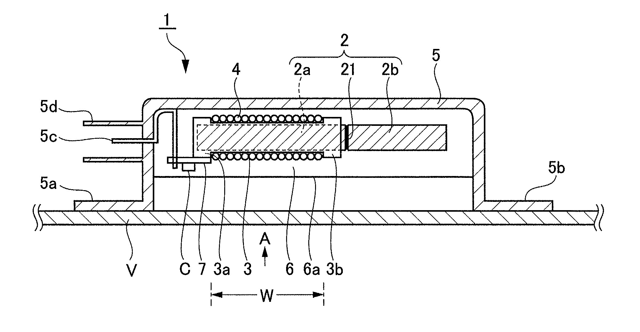
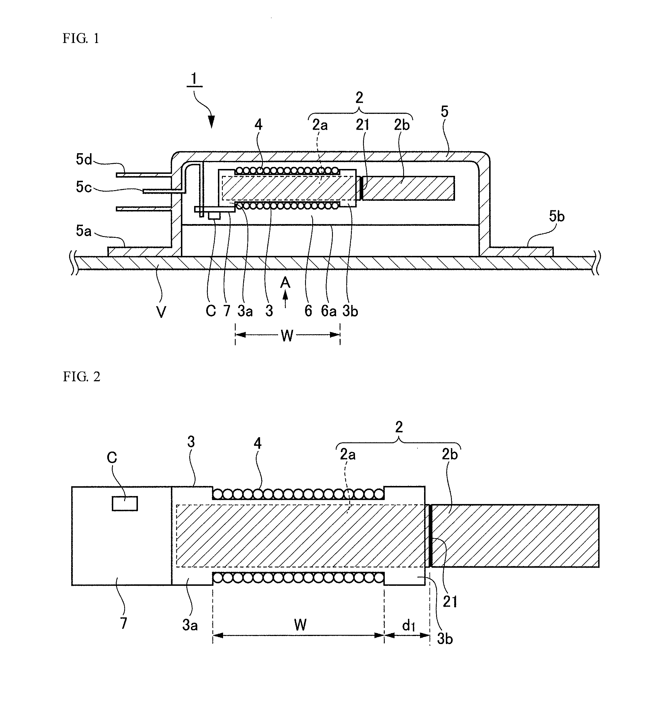
[0031]FIG. 1 is a conceptual diagram illustrating a longitudinal cross-section of a bar antenna according to the first embodiment of the present invention. FIG. 2 is a conceptual diagram illustrating a bar core, a bobbin, a winding and a printed circuit board extracted from the bar antenna according to the first embodiment of the present invention, and is viewed from an arrow A side of FIG. 1.

[0032]A bar antenna 1 includes, a bar core 2 being formed by connecting in series a first core piece 2a and a second core piece 2b having a length different from the length of the first core piece, a bobbin 3 covering the first core piece 2a only, a winding 4 being wound over a predetermined range of the bobbin 3, a case 5 having the bar core 2 and the bobbin 3 being accommodated therein, and a potting material 6 sealing the first core piece 2a and the second core piece 2b being filled in the case 5. Here, the first core piece 2a and the second core piece 2b are connected by an adhesive, and ar...

second embodiment

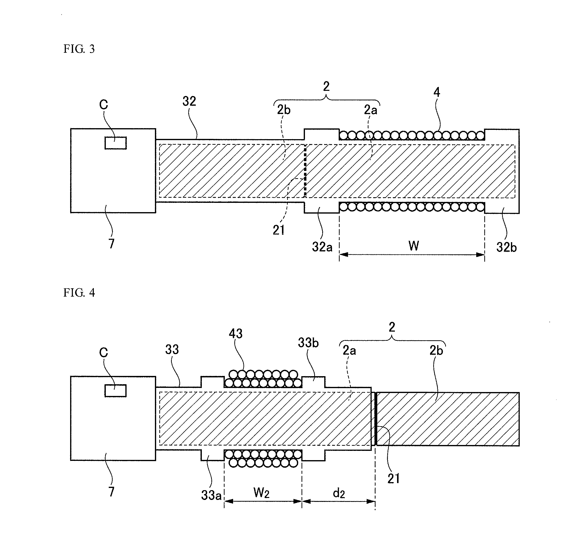
[0045]FIG. 3 is a conceptual diagram illustrating a bar core, a bobbin, a winding and a printed circuit board extracted from the bar antenna according to the second embodiment of the present invention and is viewed from an arrow A side of FIG. 1. Using the element and the sign being given thereto corresponding to the first embodiment, different points shall be described. In the second embodiment, a bobbin 32 covers almost the entire body of the bar core 2, and the printed circuit board 7 is attached to its end portion in the side of the core piece 2b. The type of the bobbin 32 in the present embodiment, in the following description, is referred to as a long bobbin, to the short bobbin as described above, sometimes.

[0046]In the above described first embodiment, the first core piece 2a and the second core piece 2b are not accommodated in the bobbin 3 which is a short bobbin, and are exposed in the case 5. On the other hand, in the present embodiment, the first core piece 2a and the se...

third embodiment

[0049]FIG. 4 is a conceptual diagram illustrating a bar core, a bobbin, a winding and a printed circuit board extracted from the bar antenna according to the third embodiment of the present invention and is viewed from an arrow A side of FIG. 1. Using the element and the sign being given thereto corresponding to the first embodiment, different points shall be described. In the third embodiment, the winding is modified to a multi-layer winding.

[0050]In the present embodiment, in the winding 43, the number of turns required to communicate at a target frequency are wound in one layer in a winding width W2 (33. Therefore, the positions of the flange 33a and the flange 33b also move the center portion of the bobbin 33.

[0051]In the present embodiment, the winding 43 is wound in a multi-layer, and the distance d2 from the connection portion 21 to the winding 43 is taken longer than the first embodiment (i.e., d2>d1). By taking such a structure, even if the slight position changes of the fi...


PUM


Abstract

A bar antenna comprises: a bar core configured to connect at least two of core pieces in series, a bobbin covering at least a portion of the bar core, a winding wound in a predetermined range of the bobbin, and a case having the bar core and the bobbin disposed therein, wherein the bar core and the bobbin are sealed by filling in the case with a potting material, and the bar core is configured to be bendable with respect to a predetermined external force at a connection portion of the at least two of core pieces.

Description

TECHNICAL FIELD[0001]The present invention is related to a bar antenna, in particular, to a bar antenna having a plurality of bar cores being divided.BACKGROUND ART[0002]Conventionally, as one of the parts which are in charge of communication functions, a bar antenna using a bar core whose material is a ferrite of a ferromagnetic material is widely used. However, the ferrite is formed by ceramics such as iron oxide mainly, and so there exists a drawback that the ferrite has a low impact resistance and is very brittle. In particular, if the bar core is formed to an elongated form having thin thickness, the bar core is broken easily sometimes. With regard to the bar antenna having the broken bar core, the inductance of the bar antenna decreases and the resonance frequency thereof changes, and so communication at a desired frequency cannot be made.[0003]Therefore, means that the bar antenna itself has a flexible structure is proposed. For example, in Japanese Laid-open Patent Applicati...

Claims


Application Information

Patent Timeline
IPC IPC(8): H01Q7/08H01Q1/40
CPCH01Q1/40H01Q7/08H01Q1/243H01Q1/32H01Q1/3291
Inventor KOGA, AKIHIROMURAKAMI, SHINSAKURADA, KUNIYOSHI
Owner MURATA MFG CO LTD
Learn More