
Brake control apparatus for vehicle

a technology for brake control and vehicle, which is applied in the direction of braking systems, instruments, analogue processes for specific applications, etc., can solve the problems of insufficient suppression of overshoot of braking torque during deceleration of electric motor, difficult to execute appropriate control, etc., and achieve the effect of reducing the amount of energization

Active Publication Date: 2015-04-23
ADVICS CO LTD
View PDF0 Cites 13 Cited by
  • Summary
  • Abstract
  • Description
  • Claims
  • Application Information

AI Technical Summary

Benefits of technology

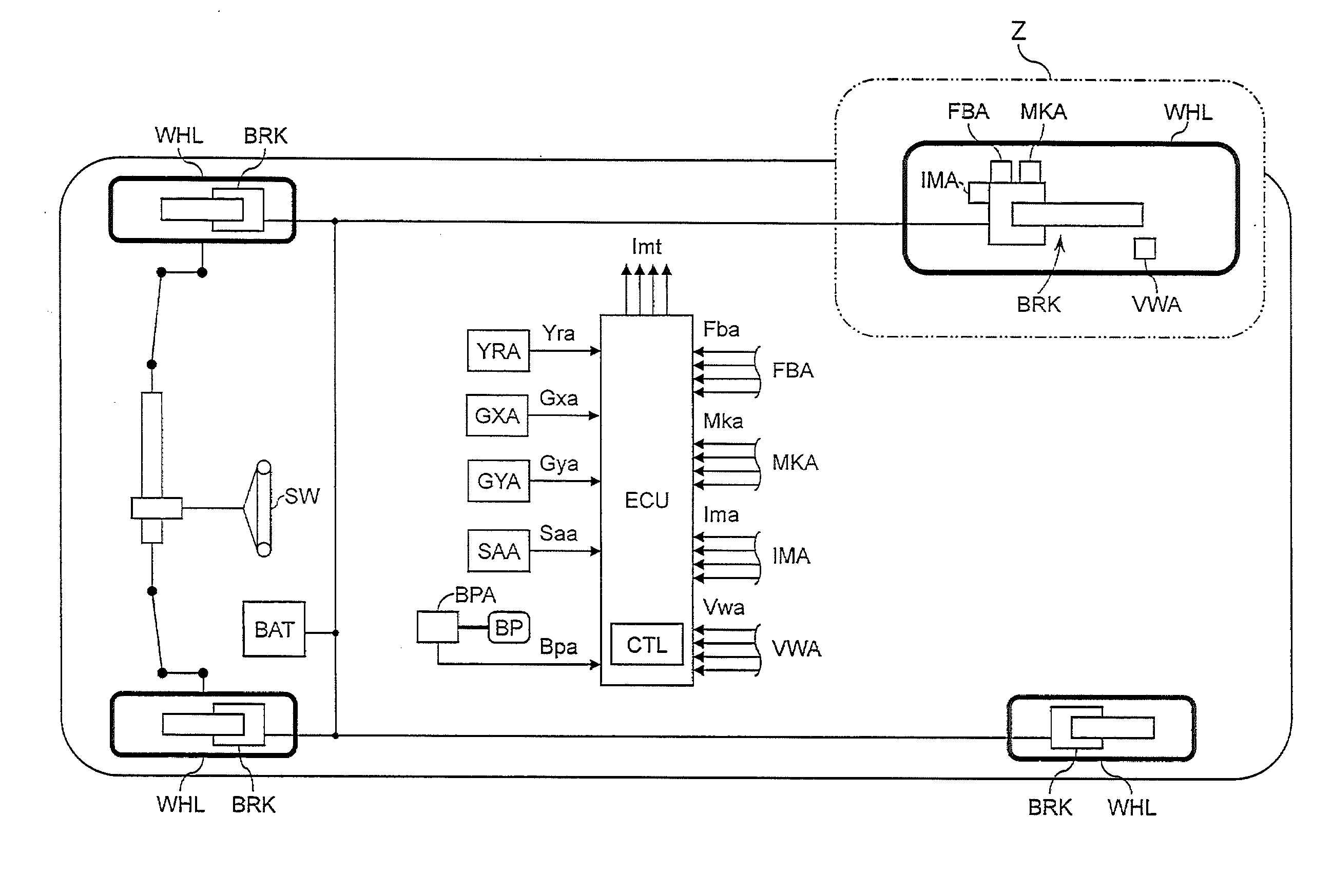
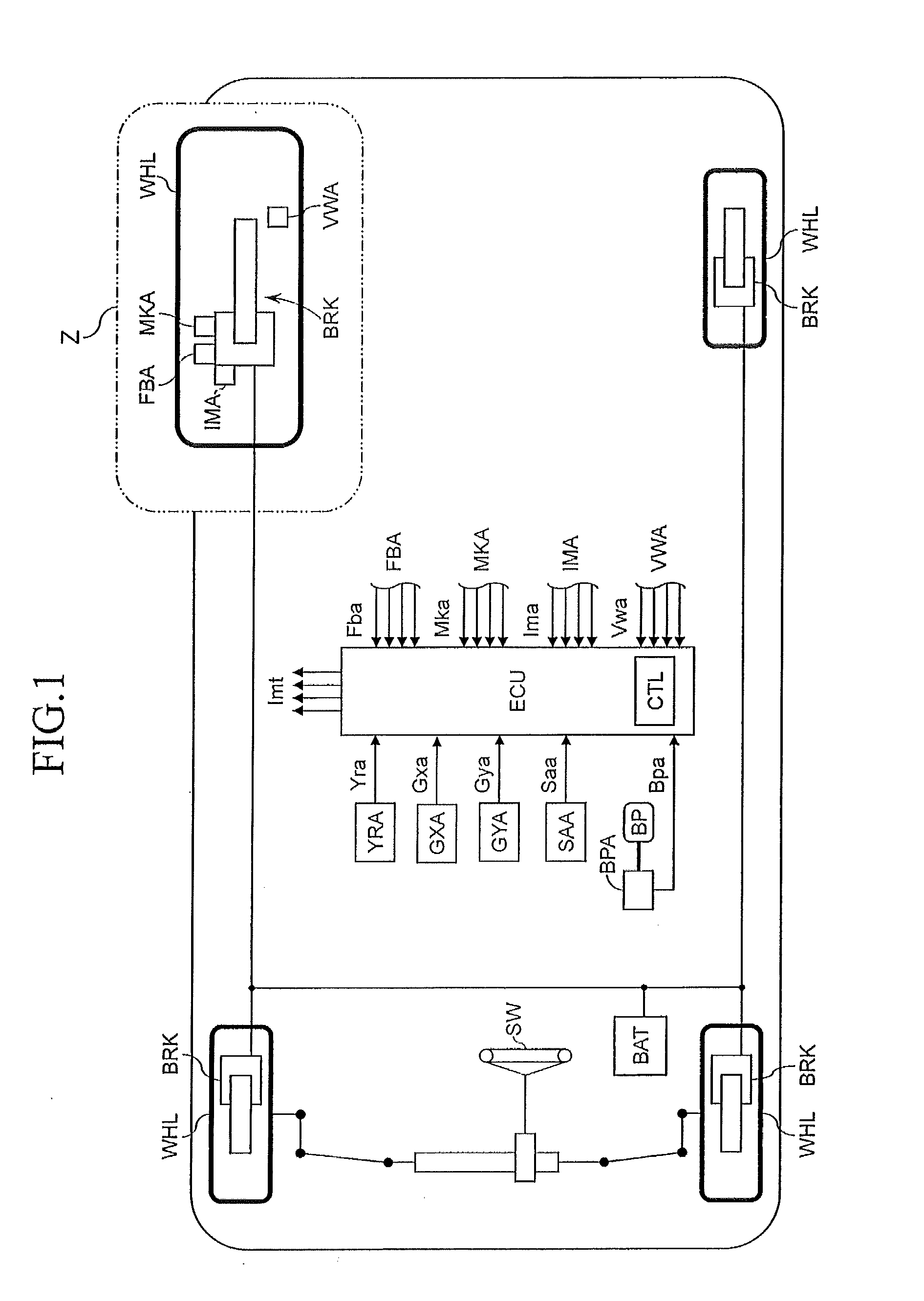
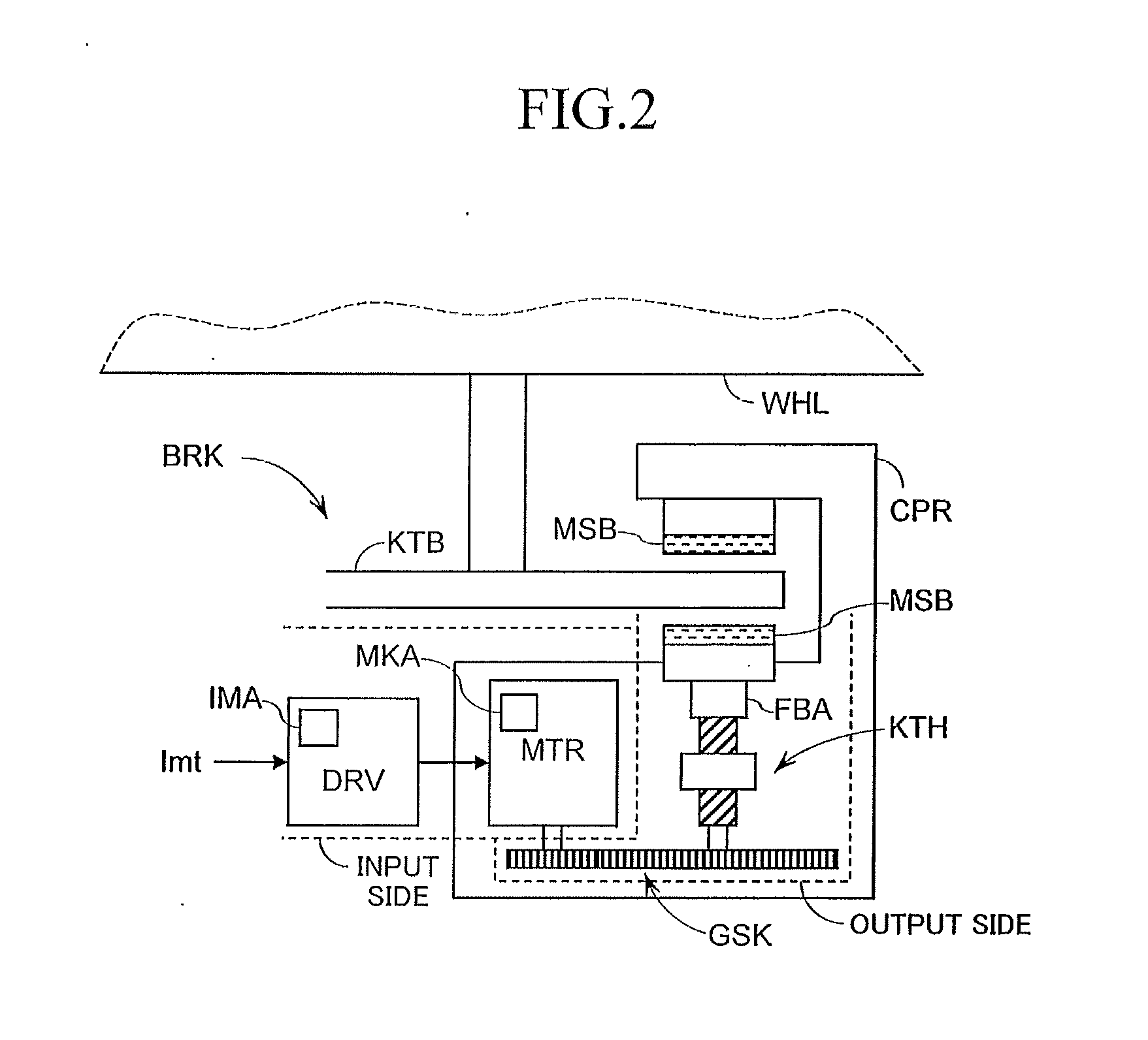
The present invention relates to a brake control device that can suppress overshoot and undershoot of braking torque during deceleration control. The device uses an inertia compensation control to accurately adjust the target value at the time of transition from the transient state to the steady state. By predicting the timing at which the actual value will transition from the transient state to the steady state, the device can adjust the target energization amount to achieve reliable control with no excess or deficiency in the energization amount. This inertia compensation control is started based on a difference between the actual value and the reference value, taking into account the time delay caused by the actual value. The device uses a step-response of the braking means as a reference to maintain the temporal relationship between the target value and the actual value.

Problems solved by technology

Therefore, in particular, in the inertia calculation control during deceleration of the electric motor, there may arise some cases where appropriate control is difficult to execute.
As a result, overshoot of a braking torque during deceleration of the electric motor cannot be sufficiently suppressed.

Method used


Image

  • Brake control apparatus for vehicle
  • Brake control apparatus for vehicle
  • Brake control apparatus for vehicle

Examples


first embodiment

Configuration of Inertia Compensation Control Block of First Embodiment

[0060]With reference to FIG. 4, the inertia compensation control block INR according to a first embodiment of the present invention is described. As illustrated in FIG. 4, the inertia compensation control block INR of the first embodiment includes a target position calculation block MKT, a control necessity determination calculation block FLG, a deceleration control start determination calculation block FLK, an inertia compensation energization amount calculation block IJK, and a selection calculation block SNK.

[0061]The target position calculation block MKT includes a conversion calculation block F2M and a limitation calculation block LMT. In the F2M, the target position (target rotation angle) Mkt is calculated based on the target pressing force Fbt and a target pressing force calculation characteristic (calculation map) CHmk. The target position Mkt is a target value of the position (rotation angle) of the ele...

second embodiment

Configuration of Inertia Compensation Control Block of Second Embodiment

[0096]Next, referring to FIG. 6, an inertia compensation control block INR according to second embodiment of the present invention is described. The inertia compensation control block INR of the second embodiment is the same as the first embodiment except for the deceleration control determination calculation block FLK. Now, only parts different from the first embodiment are described.

[0097]As illustrated in FIG. 6, the FLK of the second embodiment includes the reference value determination calculation block REF and a start determination calculation block KHE. In the REF, similarly to the case of the first embodiment, the target position (corresponding to the target value) Mkt at the time of determination of the necessary state of the deceleration control is determined as the reference value ref based on the FLr and the Mkt.

[0098]In the start determination calculation block KHE, at a time point when the actual p...

third embodiment

Configuration of Inertia Compensation Control Block of Third Embodiment

[0100]Next, referring to FIG. 7, an inertia compensation control block INR according to third embodiment of the present invention is described. The inertia compensation control block INR of the third embodiment is the same as the first and second embodiments except for the energization amount acquisition means IMA and the deceleration energization amount calculation block IKT. Now, only parts different from the first and second embodiments are described.

[0101]Even when the acceleration inertia compensation energization amount Ijt is output as a value in which the responsiveness of the electric motor MTR is taken into consideration, the actual energization amount to the electric motor MTR does not always match the target value depending on a state of the power supply voltage (for example, when a voltage drops). For example, in a case where the actual energization amount is insufficient when the electric motor MTR ...


PUM


Abstract

Electric motor control is based on a target energization amount calculated using a braking operation member operation amount. A state quantity is acquired as an actual value, indicating an actual actuation state of a movable member located in a power transmission path from the electric motor to a friction member. Using the operation amount, it is determined whether or not inertia compensation control is necessary, which compensates for the inertia influence of a brake actuator during electric motor deceleration. “A target value corresponding to the actual value” is determined as a reference value, which is calculated based on the operation amount at a time when inertia compensation control is necessary. Based on the actual and reference values, “an inertia compensation energization amount for decreasing the target energization amount to compensate for the influence of inertia” is calculated, and the target energization amount is adjusted using the inertia compensation energization amount.

Description

TECHNICAL FIELD[0001]The present invention relates to a vehicle brake control device.BACKGROUND ART[0002]Hitherto, there has been known a vehicle brake control device configured to generate a braking torque by an electric motor. In this type of device, typically, an indicator current (target current) is calculated based on an operation amount of a braking operation member for the vehicle by a driver, and the electric motor is controlled based on the indicator current. Then, a braking torque that depends on the operation of the braking operation member is applied to the wheels.[0003]In the device of this type, due to influences of the inertia (inertia moment, inertia mass) of the entire device including the inertia of the electric motor, particularly in a case of abrupt braking (upon rapid increase of braking torque) or the like, a response delay of the braking torque (a delay of rise thereof) may occur in acceleration during which the rotation speed of the electric motor is increase...

Claims


Application Information

Patent Timeline
Patent Type & Authority Applications(United States)
IPC IPC(8): B60T8/32B60T8/171B60T7/04B60T8/172
CPCB60T8/3255B60T7/042B60T8/171B60T8/172B60T13/741B60T17/22F16D65/18F16D2066/005F16D2125/40F16D2125/48
Inventor YASUI, YOSHIYUKIKODAMA, HIROYUKISATAKE, NAOTOSHI
Owner ADVICS CO LTD
Learn More