Controllable Rate Turbulating Nozzle

a turbulent nozzle and controllable technology, applied in the field of controllable rate turbulent nozzles, can solve the problems of not administering the substance, prone to deflection of spray from the centerline bore/outlet nozzle, and causing general discomfort for users

Active Publication Date: 2015-04-16
MYSTIC PHARMA INC
View PDF22 Cites 15 Cited by
  • Summary
  • Abstract
  • Description
  • Claims
  • Application Information

AI Technical Summary

Benefits of technology

The present disclosure relates to devices and methods for delivering fluids or substances through a high velocity stream of laminar flow liquid directed at a deposition target. The invention aims to improve the net delivered dose volume and minimize or eliminate the need for preservatives or bacteriostatic compounds in the delivered substances, while also ensuring the sterility of the administered substance. The devices can be designed for different types of flows and can be adjusted for different viscosities and properties of the fluid or solid being dispensed. The devices may also include bends of angles from about 1° to 90° to create the desired spray plume geometry for a particular medicament or liquid dose. Overall, the invention emphasizes the importance of the proper magnitude and vectors of velocity of the medication in creating the desired spray geometry, with a strong seal of the lid material to the blister material being critical for the success of the dispensing operation, particularly for certain dosage situations.

Problems solved by technology

High velocity and singularity of the laminar stream also imparts a general discomfort experienced by the user.
For example, the spray from centerline bore / outlet nozzles is prone to deflection by blister foil flap-type tearing.
In addition, if the unit dosage form is damaged, or is otherwise defective, the devices do not administer the substance, which may no longer be sterile.
For example, if an unit dosage form is defective in the area of the pierceable section, or develops a leak, the devices will not dispense the substance properly because sufficient pressure will not be generated in the unit dosage form to effectively release the substance.
The smaller size required by certain dosage situations, such as intranasal administration present greater challenges to the seal of the lid material to the blister material.

Method used


Image

  • Controllable Rate Turbulating Nozzle
  • Controllable Rate Turbulating Nozzle
  • Controllable Rate Turbulating Nozzle

Examples


Embodiment Construction

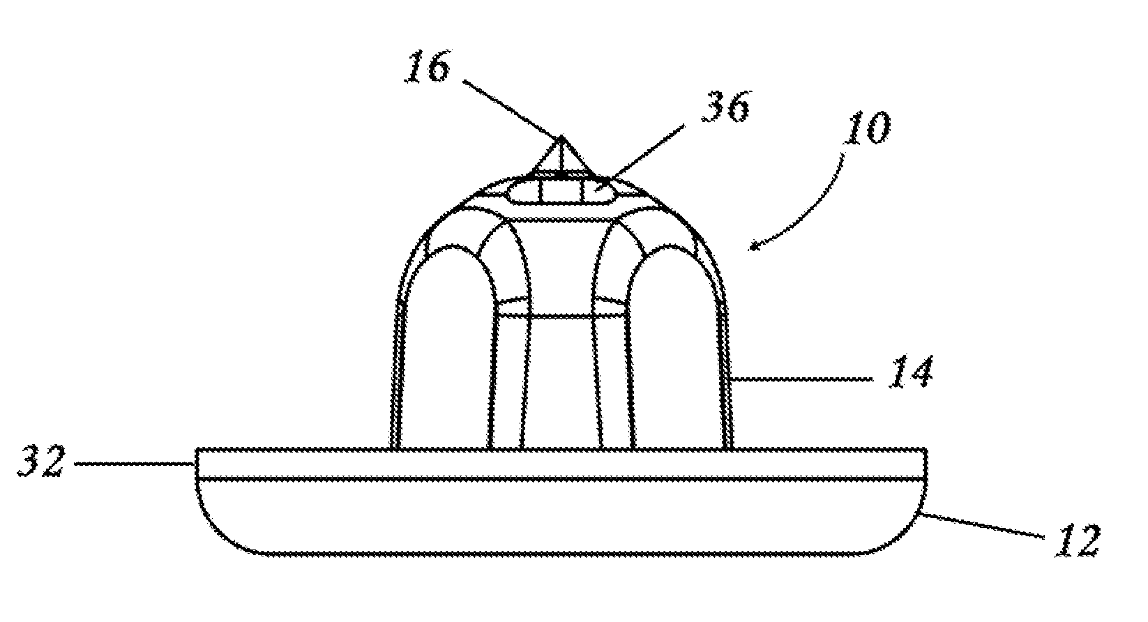
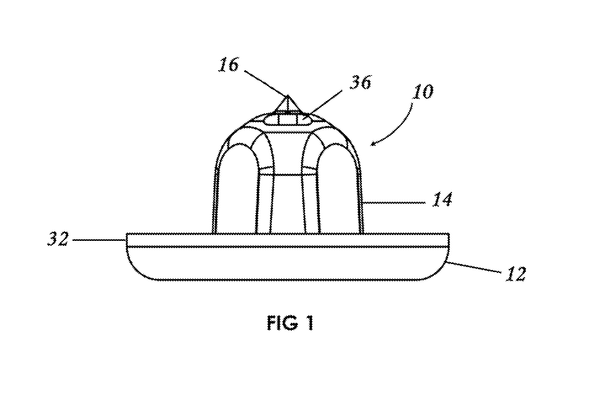
[0052]Preferred embodiments of the present disclosure are directed to dosage forms that contain a measured dose of one or more pharmaceutically active agents and a piercable section such that the dosage form can be pierced to release the contents under pressure. When using the term “under pressure” in the disclosure, it is understood that the pressure is typically an externally applied pressure rather than internal pressure within the dosage form itself. In typical operation, a plunger, lever, ram, wheel, or some other mechanical device contacts the dosage form with sufficient force to crush the dosage form against a piercing member and force the contents out of the opening. The dosage form can be generated using methods well known to those of skill in the art, including, for example, form fill seal technology or blow fill seal technology, or by deep draw forming as described in U.S. Application Publication No. 2009 / 0071108, incorporated herein in its entirety by reference.

[0053]The...


PUM


Abstract

A piercing device for use in internally pierced blister delivery devices include a base, a piercer body and an internal fluid path. The internal fluid path includes one or more inlet channels into a central cavity which is connected to one or more delivery channels and exit ports. The cavity is defined by angular walls and top to create turbulence in the fluid flow and to produce a controllable spray, mist, drops, plume or stream delivery. The piercer body also provides a pointed lancet disposed in the center of the exit ports for piercing the lidstock of a formed blister.

Description

CROSS-REFERENCE TO RELATED APPLICATIONS[0001]This application claims benefit of priority to U.S. Provisional Application No. 61 / 891,300, filed Oct. 15, 2013, the entire disclosure of which is incorporated herein by reference.STATEMENT REGARDING FEDERALLY SPONSORED RESEARCH OR DEVELOPMENT[0002]N / ABACKGROUND OF THE INVENTION[0003]There is a growing number of drugs, biologics, and liquids for which the most effective, or most convenient method of administration is by delivery of a spray or mist. A variety of devices are known for delivering a controlled amount of a pharmaceutical preparation in a spray, stream or mist to the nose, eye, ear, lungs, oral mucosal membranes, such as in the sublingual and buccal region, or throat of a user, or for topical delivery of an active agent. Various devices for nose to brain, systemic or topical delivery of a liquid or even a powdered formulation include a measured amount of a pharmaceutical composition contained in a crushable ampoule, blister or ...

Claims


Application Information

Patent Timeline
IPC IPC(8): A61M15/00A61M35/00A61M31/00A61M11/00A61F9/00
CPCA61M15/0036A61M11/008A61F9/0008A61M31/00A61M35/003A61M2202/04A61M2202/064A61M2210/04A61M2210/0612A61M2210/0618A61M2210/0662A61M15/0061
Inventor HANCOCK, JESSE RYANSHAW, MICHAEL
Owner MYSTIC PHARMA INC
Why Eureka
Try Eureka