Eureka AIR delivers breakthrough ideas for toughest innovation challenges, trusted by R&D personnel around the world.

Solid oxide fuel cell stack

a fuel cell and solid oxide technology, applied in the direction of fuel cells, fuel cell details, electric generators, etc., can solve the problems of long time required to reduce the temperature, insufficient space left for the installation of the fuel cell system, and difficulty in installation, so as to achieve excellent power generation performance and reduce electrical resistance

Inactive Publication Date: 2015-04-02
TOTO LTD
View PDF12 Cites 0 Cited by
  • Summary
  • Abstract
  • Description
  • Claims
  • Application Information

AI Technical Summary

Benefits of technology

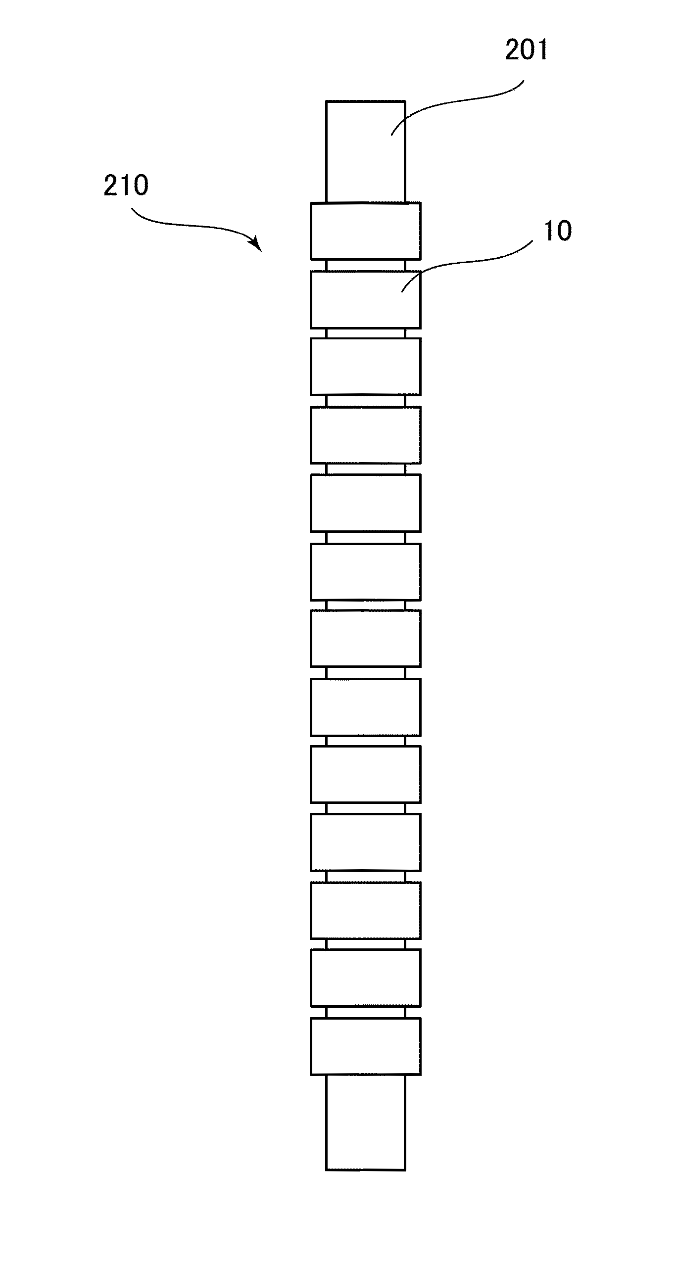
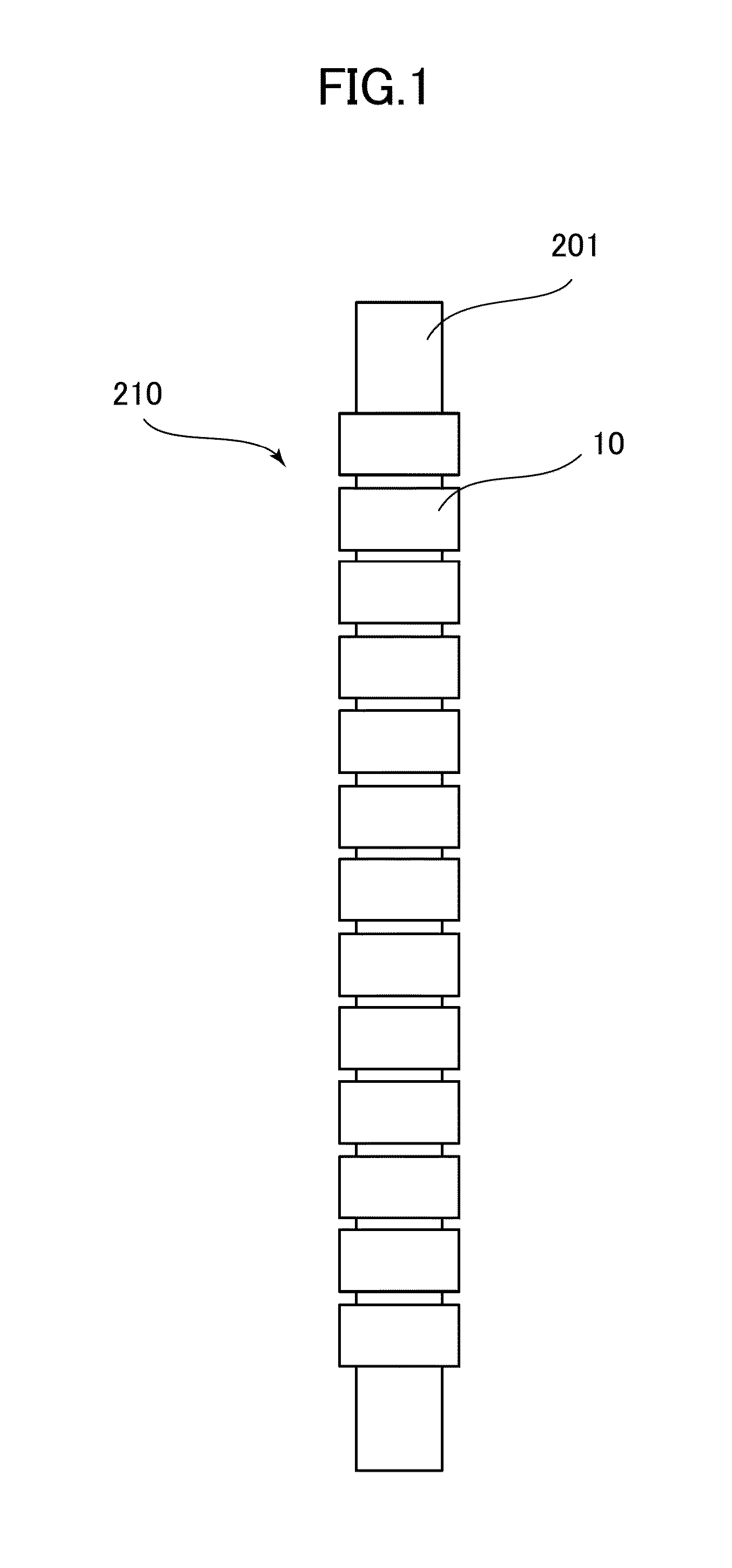
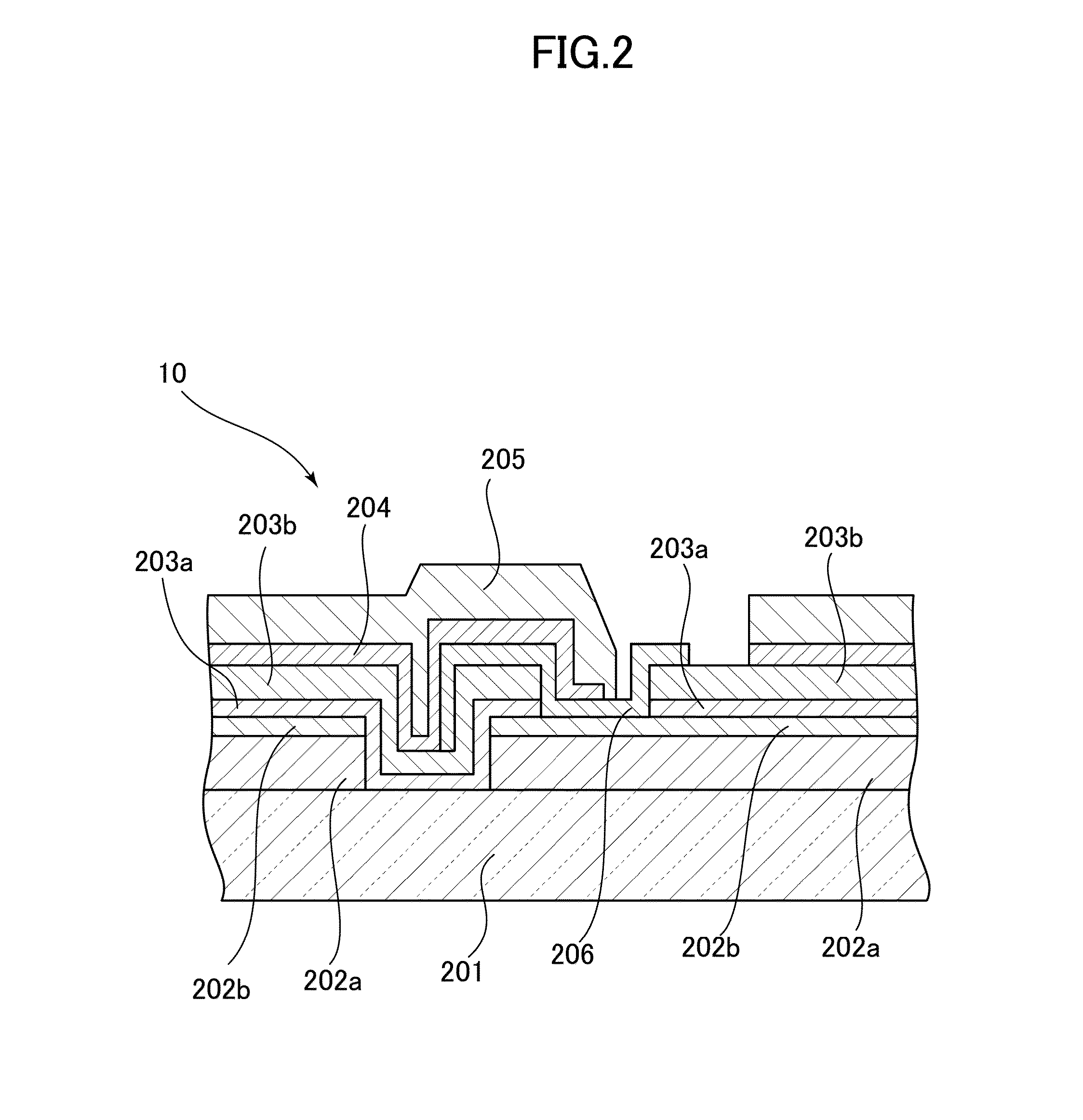
[0022]According to the present invention, a solid oxide fuel cell stack comprising a plurality of power generating elements electrically connected to each other on

Problems solved by technology

Since most part of the solid oxide fuel cell stack is the insulating support, a module constituted of the solid oxide fuel cell stack in which the insulating support is made of calcia-stabilized zirconia (CSZ) tends to require a long time to increase the temperature of the module by an activation operation from around room temperature to a temperature at which electrical power can be generated, and also require a long time to decrease the temperature thereof by a stop operation from the power-generating temperature to around room temperature.
Moreover, a fuel cell system using the solid oxide fuel cell stack comprising calcia-stabilized zirconia (CSZ) having a high specific gravity as the insulating support tends to have a heavy weight.
When installed in an existing house, the fuel cell system is often installed near an existing water heater of the house and there is not enough space left for the fuel cell system to be installed.
Accordingly, the weight increase possibly makes such installation difficult in some cases.
Further, calcia-stabilized zirconia (CSZ) has a

Method used


Image

  • Solid oxide fuel cell stack
  • Solid oxide fuel cell stack
  • Solid oxide fuel cell stack

Examples


example 1

Preparation of Green Body for Insulating Support

[0054]A high purity forsterite (Mg2SiO4 raw material containing a Mg element and a Si element with a concentration of 99.5 mass % in total in terms of MgO and SiO2, and a Ca element with a concentration of 0.05 mass % in terms of CaO) powder was adjusted to have an average particle diameter of 0.7 μm. After 100 parts by weight of the powder was mixed with 20 parts by weight of a solvent (water), 8 parts by weight of a binder (methyl cellulose), 0.5 parts by weight of a lubricant, and 15 parts by weight of a pore forming agent (acrylic resin particles having an average particle diameter of 5 μm) using a high-speed mixer, the mixture was kneaded with a kneader and deaerated with a vacuum kneader. Thus, a green body for extrusion was prepared. Here, the average particle diameter was measured according to JIS R 1629, and expressed in a 50% diameter (the same applies hereinafter).

(Preparation of Paste for Fuel Electrode Layer)

[0055]A NiO po...

example 2

Preparation of Green Body for Insulating Support

[0075]A high purity forsterite (Mg2SiO4 raw material containing a Mg element and a Si element with a concentration of 99.5 mass % in total in terms of MgO and SiO2, and a Ca element with a concentration of 0.02 mass % in terms of CaO) powder was adjusted to have an average particle diameter of 0.7 μm. After 100 parts by weight of the powder was mixed with 20 parts by weight of a solvent (water), 8 parts by weight of a binder (methyl cellulose), 0.5 parts by weight of a lubricant, and 15 parts by weight of a pore forming agent (acrylic resin particles having an average particle diameter of 5 μm) using a high-speed mixer, the mixture was kneaded with a kneader and deaerated with a vacuum kneader. Thus, a green body for extrusion was prepared. Here, the average particle diameter was measured according to JIS R 1629, and expressed in a 50% diameter.

(Preparation of Paste for Fuel Electrode Layer)

[0076]A paste for fuel electrode layer was pr...

example 3

[0087]Example 3 was conducted in the same manner as in Example 1, except that the high purity forsterite used to prepare a green body for insulating support had a CaO concentration of 0.3 mass %.

(Power Generation Test)

[0088]Using the obtained solid oxide fuel cell stack, a power generation test was conducted under the same conditions as those in Example 1. As a result, the solid oxide fuel cell stack of Example 3 had an OCV (0.0 A / cm2) of 1.08 V, the electric potential per power generating element at a current density of 0.20 A / cm2 was 0.81 V, and the electric potential per power generating element at a current density of 0.40 A / cm2 was 0.63 V. Hence, favorable power generation results were obtained.

[0089]A stack was prepared by bundling 72 solid oxide fuel cell stacks obtained in the above-described manner. The time required for the activation operation of the stack thus prepared was shortened to approximately 2 / 3 (67%) of that of the conventional stack (prepared using cell stacks ...


PUM


Abstract

Provided is a solid oxide fuel cell stack including: a porous insulating support having a gas permeability and provided with a gas flow path therein; and a plurality of power generating elements which are provided on the insulating support and each of which includes an inner electrode, an electrolyte. An outer electrode, the inner electrode, the electrolyte and the outer electrode are sequentially laminated one another, and the inner electrode of one of adjacent two of the plurality of power generating elements is electrically connected to the outer electrode of the other of the adjacent two of the plurality of power generating elements via an interconnector, so that the plurality of power generating elements are connected in series, wherein the insulating support comprises forsterite, the insulating support contains a Mg element and a Si element with a concentration of 90 mass % or more in total in terms of MgO and SiO2, at least in a surface region on the power generating elements side, and the interconnector comprises titanium-based perovskite type oxide represented by (A,B)(Ti,C)O3-δ.

Description

RELATED APPLICATIONS[0001]This application claims priority under 35 U.S.C. §119 to Japanese Patent Application No. 2013-200862 filed on Sep. 27, 2013, the entire content of which is hereby incorporated by reference.BACKGROUND OF THE INVENTION[0002]1. Field of the Invention[0003]The present invention relates to a horizontal stripe type fuel cell stack with more reliable electrical connection between cells.[0004]2. Description of the Related Art[0005]In a solid oxide fuel cell (hereinafter also referred to as “SOFC”), an oxide ion conductor is used as an electrolyte, and electrodes are attached to both sides of the electrolyte. A fuel gas is supplied to one of the sides, and an oxidizing agent gas (air, oxygen, or the like) is supplied to the other side. In this manner, the fuel cell operates at relatively high temperature.[0006]A conventional horizontal stripe type fuel cell stack comprises: a porous insulating support having a gas permeability and provided with a gas flow path there...

Claims


Application Information

Patent Timeline
IPC IPC(8): H01M8/24H01M8/00H01M8/02H01M8/12
CPCH01M8/2465H01M8/1286H01M8/2425H01M2008/1293H01M8/0236H01M8/1226H01M8/006H01M8/0217H01M8/1231Y02E60/50
Inventor ANDO, SHIGERUWATANABE, NAOKIHOSHIKO, TAKUYATANAKA, SHUHEISATO, MASAKIISAKA, NOBUOMOMIYAMA, YUTAKAFURUYA, SEIKIHAYAMA, KIYOSHIKAKINUMA, YASUOOKAMOTO, OSAMU
Owner TOTO LTD
Why Eureka
Eureka Blog
Learn More