Method for Forming Oxide Film by Plasma-Assisted Processing

Active Publication Date: 2015-03-19
ASM IP HLDG BV
View PDF14 Cites 283 Cited by
  • Summary
  • Abstract
  • Description
  • Claims
  • Application Information

AI Technical Summary

Benefits of technology

The patent text describes a method of using CxOy and / or NxOy to inhibit oxidation of an underlying layer and prevent particles from being generated during deposition. By using these alternatives to oxygen, the process also avoids clogging of lines and increases the efficiency of deposition. The method also allows for the formation of a high-quality oxide film that has a high affinity with nitride films, which has applications in the formation of film capacitors. Overall, this method improves the quality and efficiency of the deposition process while also increasing throughput.

Problems solved by technology

In a PEALD process, depending on the type of application, there are problems to be solved, such as oxidation of an underlying layer and auto-doping in a process of boron-silicate glass (BSG) / phosphor-silicate glass (PSG).
That is, although a portion of BSG / PSG film is removed from an area where diffusion of dopant is not desired during and after a deposition step, and then heat treatment of the substrate is conducted so that the diffusion of impurities can be confined only to a certain area in the substrate, the unwanted diffusion of impurities will result in another area of the substrate if the diffusion occurs during deposition when high RF power is applied.
Further, low RF power is required in a SiO process where oxidation of an underlying layer 7 is undesired because, as illustrated in FIG. 1b when high RF power is applied, the underlying layer 7 is oxidized due to the effects of oxygen plasma, ion bombardment, and sputtering during film deposition.

Method used


Image

  • Method for Forming Oxide Film by Plasma-Assisted Processing
  • Method for Forming Oxide Film by Plasma-Assisted Processing
  • Method for Forming Oxide Film by Plasma-Assisted Processing

Examples


reference examples 1 and 2

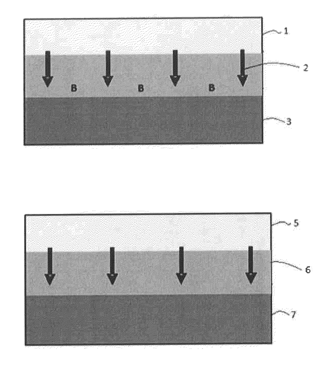
[0041]In order to evaluate the degree of oxidation caused by an oxygen plasma (Reference Example 1) and a carbon dioxide plasma (Reference Example 2), naked Si substrates were exposed to an oxygen plasma and a carbon dioxide plasma, respectively, without supplying a precursor (without depositing an oxide film) thereon so that the degree of oxidation by each plasma could be evaluated in an accelerated manner based on a thickness of SiO generated by oxidizing the surface of the naked Si substrate by the plasma. It is considered that in depositing an oxide film, at least in the beginning of the deposition process, phenomena similar to those observed in Reference Examples 1 and 2 occur.

[0042]A naked Si substrate was loaded in an apparatus illustrated in FIG. 4 and exposed to a plasma under conditions shown in Table 3 below.

TABLE 3Reactant gas flow (continuous)O2 or CO2; 1200 sccmAuxiliary gas flow (continuous)Ar; 2400 sccmHe; 100 sccmProcess temperature300° C.Pressure250 PaRF power (13....

example 4

[0048]An oxide film was deposited on a substrate by PEALD under the conditions which were the same as in Example 2, except that the bottle was heated to 50° C. (thereby increasing the feed of the precursor). As a result, the growth rate was increased to 0.132 nm / cycle. However, the number of particles detected was less than 10, indicating that even when the feed was increased while maintaining the short purge time (0.1 seconds), the number of particles detected can remain extremely low.

reference example 3 and 4

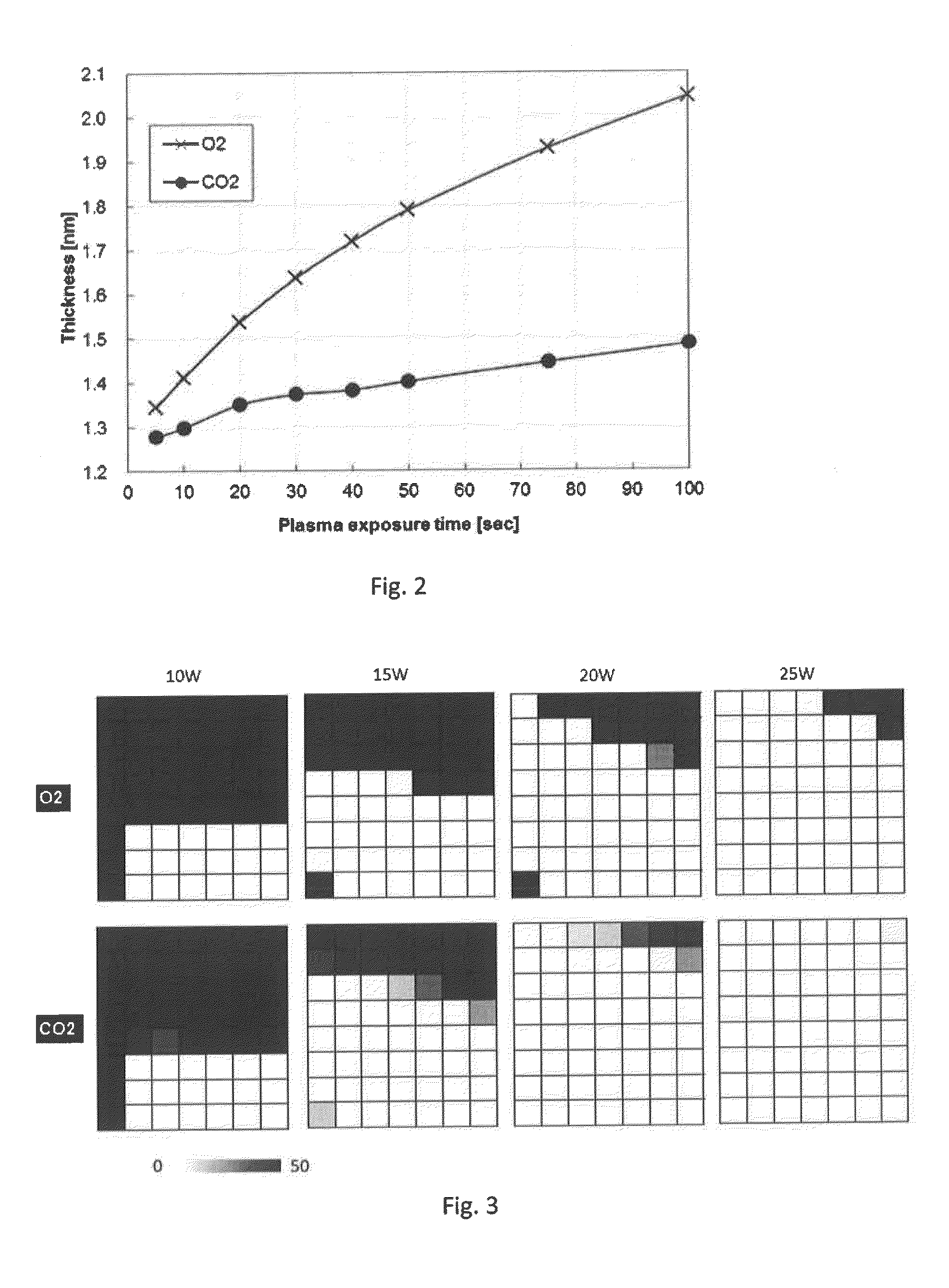
[0049]In order to evaluate a plasma ignition range using oxygen (Reference Example 3) and carbon dioxide (Reference Example 4), the ignition state was checked using the apparatus illustrated in FIG. 4 based on multiple matrixes each defined by a vertical axis which is pressure [Pa] (the rows correspond to 222, 250, 300, 400, 500, 600, 700, and 800 Pa, respectively) and a horizontal axis which is a gap [mm] between the electrodes (the columns correspond to 9.5, 11, 12, 13, 14, 15, and 16 mm, respectively) when 10 W, 15 w, 20 W, and 25 W of RF power were applied to the respective matrixes. The results are shown in FIG. 3. Each cell in each matrix shows the number of ignition failures per 50 attempts using a gray scale from the lightest representing no ignition failure to the darkest representing 50 occurrences of ignition failure. As shown in FIG. 3, there is no significant difference in ignitability between oxygen and carbon dioxide, indicating that carbon dioxide can ignite a plasma...


PUM

PropertyMeasurementUnit
Poweraaaaaaaaaa

Abstract

A method for forming an oxide film by plasma-assisted processing includes: (i) supplying a precursor reactive to none of oxygen, CxOy, and NxOy (x and y are integers) without a plasma to a reaction space wherein a substrate is placed; (ii) exposing the precursor to a plasma of CxOy and / or NxOy in the reaction space; and (iii) forming an oxide film on the substrate using the precursor and the plasma.

Description

BACKGROUND OF THE INVENTION[0001]1. Field of the Invention[0002]The present invention generally relates to a method for forming an oxide film of a metal or silicon by plasma-assisted processing such as plasma-enhanced atomic layer deposition (PEALD).[0003]2. Description of the Related Art[0004]In a PEALD process, depending on the type of application, there are problems to be solved, such as oxidation of an underlying layer and auto-doping in a process of boron-silicate glass (BSG) / phosphor-silicate glass (PSG). Conventionally, these problems have been handled by lowering RF power.[0005]For example, low RF power is required in the BSG / PSG process for solid state diffusion (SSD) because, as illustrated in FIG. 1a when high RF power is applied, penetration of dopant (boron) 2 into a Si substrate 3 occurs during deposition of a BSG film 1 due to the ion bombardment effect. That is, although a portion of BSG / PSG film is removed from an area where diffusion of dopant is not desired during...

Claims


Application Information

Patent Timeline
IPC IPC(8): C23C16/505C23C16/40
CPCC23C16/401C23C16/505C23C16/405C23C16/4554C23C16/5096H01L21/02112H01L21/02164H01L21/02186H01L21/02211H01L21/02219H01L21/02274H01L21/0228
Inventor NAKANO, RYUINOUE, NAOKI
Owner ASM IP HLDG BV
Why Eureka
Try Eureka