
Flexible response secured mechanical balancing for multiple control actuators with a common output

a technology of mechanical balancing and actuators, applied in the direction of servomotor parallel arrangements, fluid couplings, clutches, etc., can solve the problems of fatigue load accumulation, inability to use electronic balancing devices, and the potential for a resultant force fight between active and active operation modes, so as to achieve high accuracy and reduce friction

Active Publication Date: 2015-03-19
AIRBUS HELICOPTERS DEUT GMBH
View PDF6 Cites 4 Cited by
  • Summary
  • Abstract
  • Description
  • Claims
  • Application Information

AI Technical Summary

Benefits of technology

The present invention provides a fluid-pressure balancing device that includes a cylinder bore and a slidably movable piston for opening a connection port to a pressure relief line to relieve pressure in the affected fluid-pressure network. The device also includes a flow restrictor in the tap line to damp instable fluid-pressure feeding of the piston. The cylinder bore is sealed with the piston through high accuracy direct mating, with reduced friction. The device provides independent fluid-pressure networks and allows for commanding the actuator system in a passive-active operational mode.

Problems solved by technology

In theory, the active-active operational mode does present the potential for a resultant force fight between the active actuators controlling the common output members.
Although, the still existing differences as well as further shifts during operation, e.g. due to wear, can result in one independent fluid-pressure network to attempt to position one of the common output members towards a different location than the position attempted by another independent fluid-pressure network.
This differential and antagonistic force or torsion moment introduces stress to the common parts of the actuators and do result in a fatigue load accumulation.
In some types of aircrafts, such electronic balancing devices cannot be used due to the electronic environment (e.g. existing / basic architecture) for the aircraft that cannot provide a convenient interface.
Another problem is related to existing mechanical balancing devices.
In some available mechanical balancing devices, having a spring loaded relief valve function integrated into by-pass valves, the mechanical balancing device can only provide a monolithic relief against a single pre-determined level of pressure, defined by the mechanic characteristics of the relevant spring.
Therefore, a flexible (i.e. adaptive or variable) balancing of different pressure levels, creating forces below / above a pre-determined / single spring force, is not available with present mechanical balancing devices.
A further problem relates to some operation modes.
In some aircraft control systems having a mechanical balancing device, should an “active-passive” operation mode be implemented, this would render the active pressure impossible to be used by the actuator.
But the prior art mechanical balancing devices do not allow the “active-passive” operation modes.
This would render the active pressure impossible to be used by the actuator coupled to the independent fluid-pressure networks.
Consequently, these prior art devices does not meet the pre-requisites for safe operation required by airworthiness regulations.
No fail-safe mechanism for active-passive operation mode seems available.
So, during such operation mode, the valve would maintain to balance the pressure of the active network against the passive one, which would render the active pressure impossible to be used by the actuator.
Despite the valuable enhancements brought to prior art mechanical balancing devices, limits and drawbacks remain for multiple fluid-pressure control actuators system and vehicles operated thanks to such devices and systems.

Method used


Image

  • Flexible response secured mechanical balancing for multiple control actuators with a common output
  • Flexible response secured mechanical balancing for multiple control actuators with a common output
  • Flexible response secured mechanical balancing for multiple control actuators with a common output

Examples


Embodiment Construction

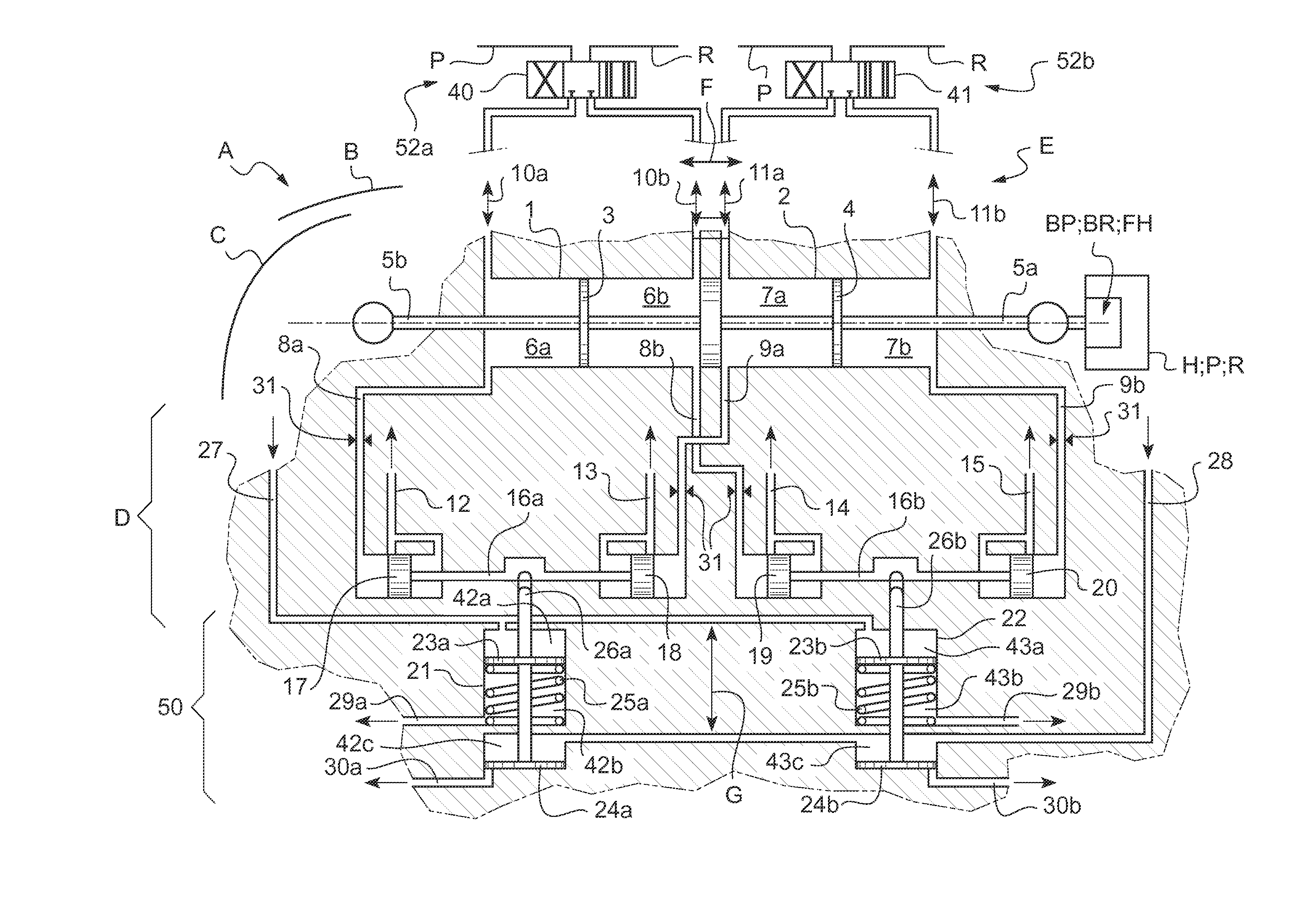
[0069]A detailed description of illustrated embodiments follows. In Figures drawings, similar elements are given the same reference numerals.

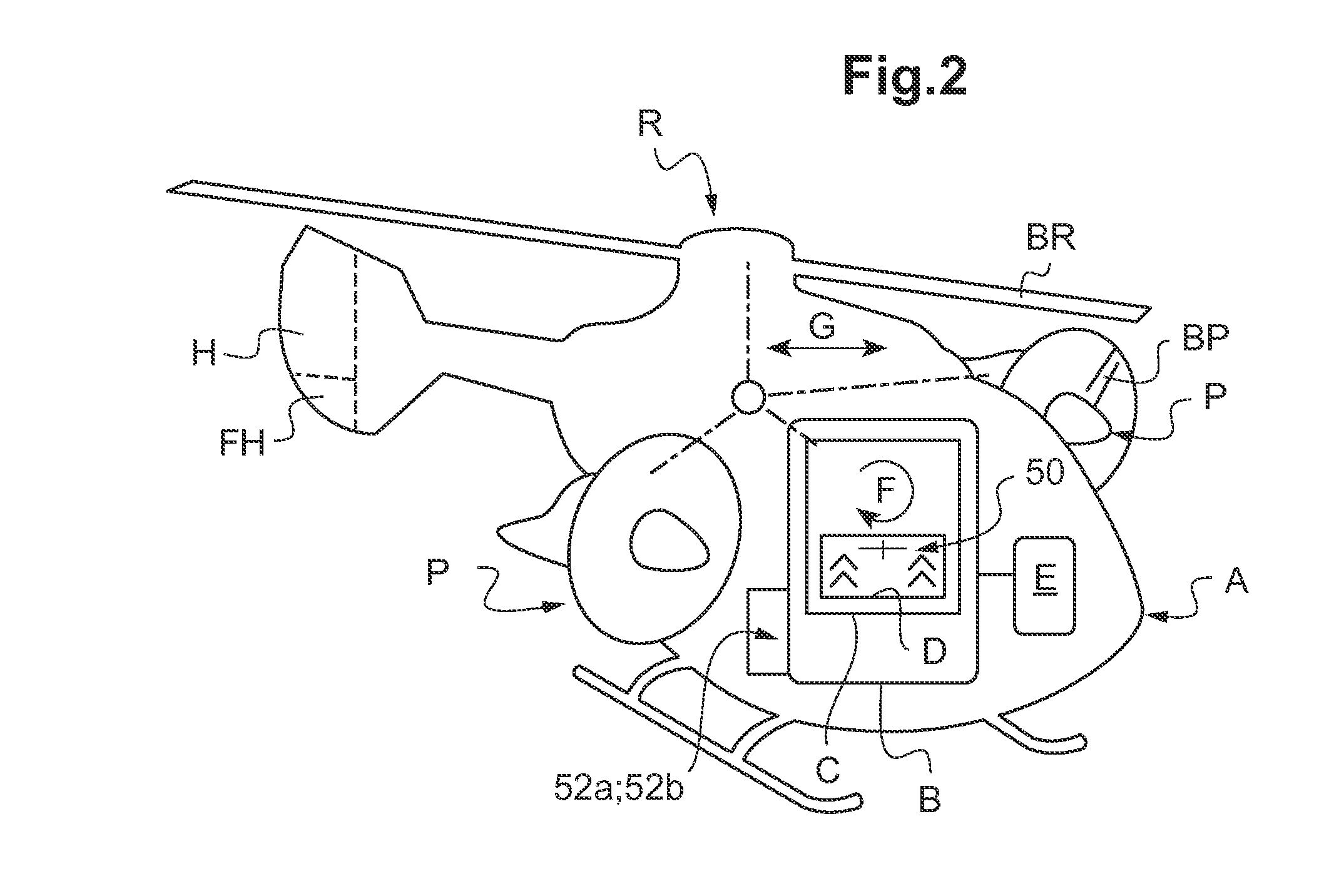
[0070]Generally speaking, on FIGS. 1 and 2, the reference A designates a vehicle.

[0071]On examples of FIGS. 1 and 2, such vehicles A are aircrafts. But the invention is obviously useful to many other types of vehicles A, not only aircrafts or vehicles A including hovering / propelling blades. The vehicle A of FIG. 2 is a rotorcraft, thus including a hovering arrangement R with a main rotor having a plurality of hovering surfaces BR, e.g. rotor blades. From FIG. 2, the aircraft vehicle A is also including a pair of propelling arrangements P: the example vehicle A of FIG. 2 is a so-called hybrid helicopter. This example vehicle A is further equipped with a plurality of flight control arrangements H such as flaps, stabilizers or the like, designated as FH.

[0072]On FIG. 2, each propelling arrangement P has a plurality of propelling surfaces BP, e.g. ...


PUM


Abstract

A flexible response secured mechanical balancing device (D) for multiple hydraulic control actuators (1-2) with a common output member (5a-b). The balancing device (D) provides flexible / continuous fluid-pressure force fight compensation. Balance valves (17-20) are commanded to balance fluid-pressure from a first fluid-pressure network (52a) of a second actuator (2). Each fluid-pressure commanded balance valve (17-20) is arranged to allow relief of differential pressure, directly into a dedicated first (52a) or second fluid-pressure network (52b). A fluid-pressure controlled locking device (21-22) is allowing inhibiting the corresponding pairs of balance valves (17-20) e.g. in case of loss of fluid-pressure. The invention typically applies to vehicles (A) including: aircrafts, rotorcrafts, drones.

Description

CROSS REFERENCE TO RELATED APPLICATION[0001]This application claims priority to European patent application No. 13 400019.9 filed on Sep. 17, 2013, the disclosure of which is incorporated in its entirety by reference herein.BACKGROUND OF THE INVENTION[0002](1) Field of the Invention[0003]The invention concerns a flexible response secured mechanical balancing device for a multiple fluid-pressure control actuators system in a vehicle.[0004](2) Description of Related Art[0005]The most general technical domain of the invention is the one of fluid-pressure actuators, e.g. of the hydraulic type, for displacing one or a plurality of output members between two extreme positions. Depending on applications, this displacement is either linear or rotational.[0006]The invention concerns multiple fluid-pressure actuators, i.e. wherein a plurality of fluid-pressure actuators cooperate together so as to produce a power force capable of displacing a set of output members, either with a linear motion...

Claims


Application Information

Patent Timeline
IPC IPC(8): F15B15/02
CPCF15B15/02F15B18/00F15B2211/8757
Inventor PAULMANN, GREGOR
Owner AIRBUS HELICOPTERS DEUT GMBH
Learn More