
Plasma processing device and plasma processing method

a plasma processing and processing device technology, applied in the direction of electrical equipment, basic electric elements, electric discharge tubes, etc., can solve the problems of difficult suppression of the etching rate of the target substrate of the first lot, and achieve the effect of suppressing the reduction of the throughput of the plasma process of the target substra

Active Publication Date: 2015-03-05
TOKYO ELECTRON LTD
View PDF16 Cites 228 Cited by
  • Summary
  • Abstract
  • Description
  • Claims
  • Application Information

AI Technical Summary

Benefits of technology

The present invention is about a plasma processing device and method that can maintain the etching rate of target substrates while increasing the throughput of plasma processing. This means that the device and method can improve productivity while also ensuring consistent and efficient processing.

Problems solved by technology

For that reason, in the related art, it is difficult to suppress a reduction in the etching rate of target substrates of the first lot while suppressing a reduction in the throughput of a plasma process of target substrates.

Method used


Image

  • Plasma processing device and plasma processing method
  • Plasma processing device and plasma processing method
  • Plasma processing device and plasma processing method

Examples


Embodiment Construction

[0028]Embodiments will now be described with reference to the drawings. In the respective drawings, identical or equivalent parts will be designated by like reference symbols.

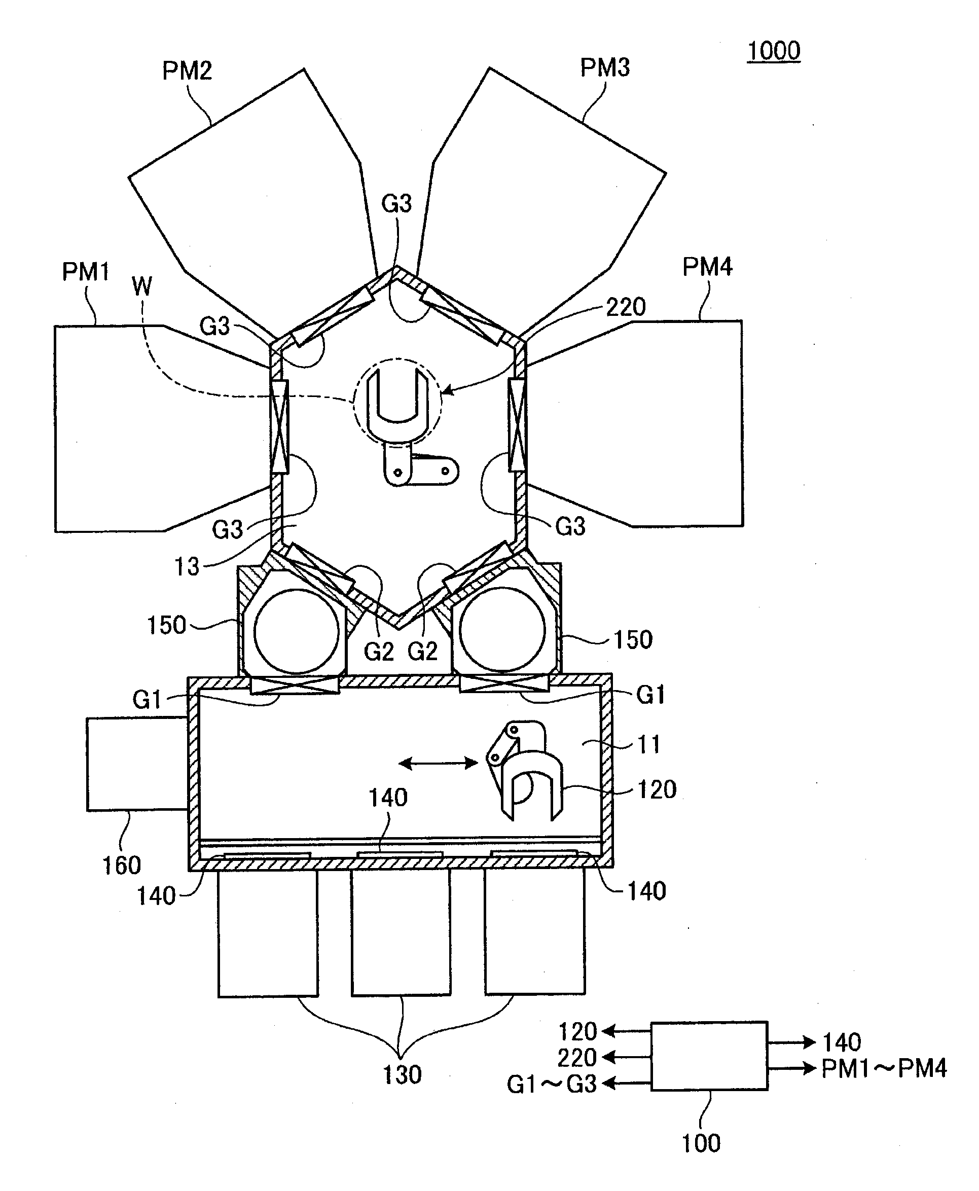
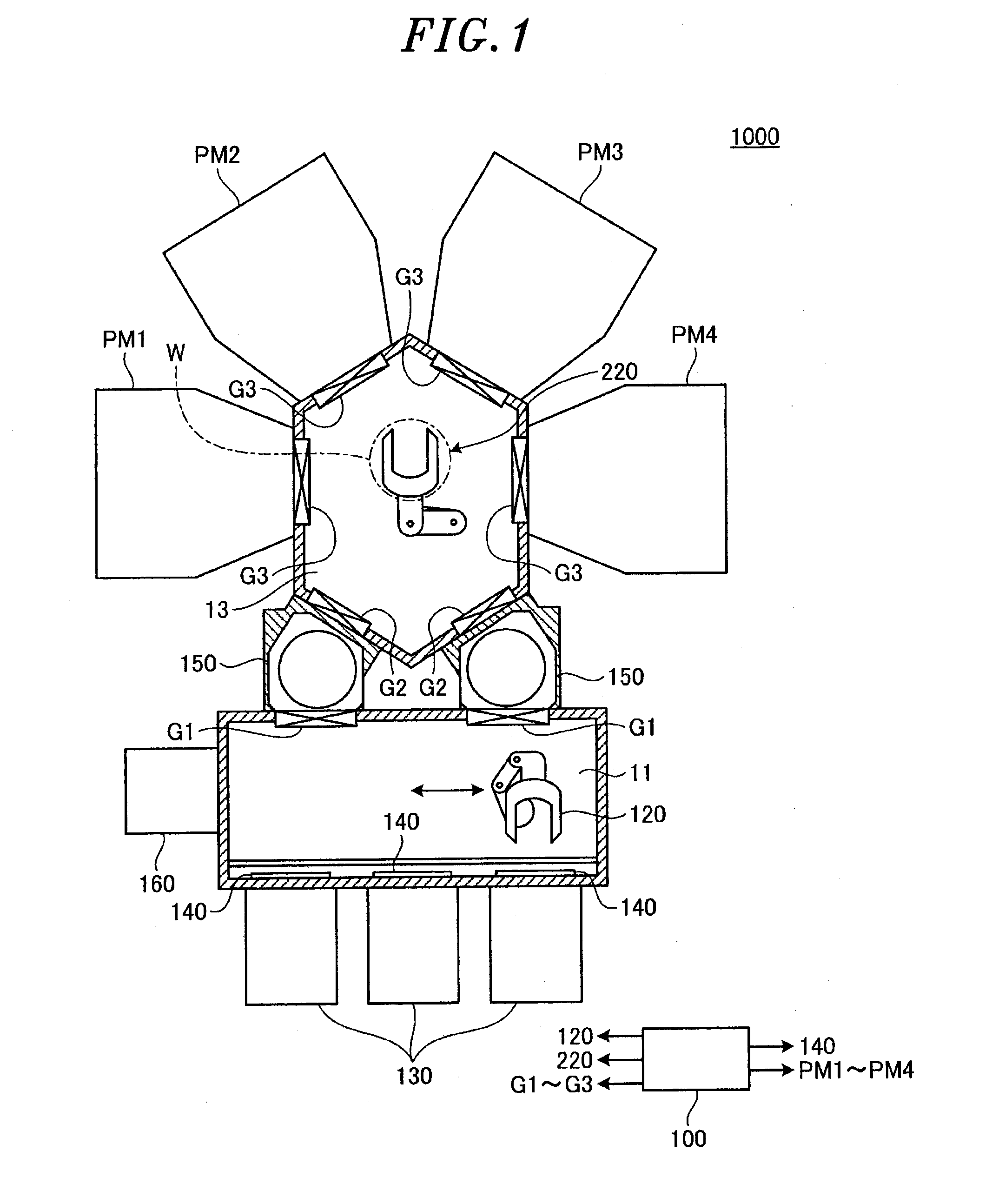
[0029]FIG. 1 is a view schematically showing a plasma processing system according to an embodiment. As shown in FIG. 1, the plasma processing system 1000 according to the embodiment includes an atmospheric transfer chamber 11, loading and unloading ports 130, load-lock chambers 150 and an alignment module 160. The plasma processing system 1000 further includes a vacuum transfer chamber 13, a plurality of plasma processing devices PM1 to PM4 and a control unit 100.

[0030]The atmospheric transfer chamber 11 is a rectangular parallelepiped transfer container which is kept under an atmospheric pressure and which is designed to transfer a target substrate W placed in each of the loading and unloading ports 130 to, e.g., the plasma processing device PM1. Within the atmospheric transfer chamber 11, there is provided a ...


PUM

PropertyMeasurementUnit
frequencyaaaaaaaaaa
temperatureaaaaaaaaaa

Abstract

A plasma processing device includes a processing chamber defining a plasma processing space and a stage for mounting thereon a target substrate in the processing chamber. The plasma processing device further includes a gas supply mechanism for introducing a processing gas into the plasma processing space, a plasma generation mechanism for supplying electromagnetic energy into the plasma processing space, and a control unit configured to, if a command to start a plasma process for the target substrate mounted on a substrate carry-in stage is issued, perform a warm-up process for supplying the processing gas into the plasma processing space by the gas supply mechanism and supplying the electromagnetic energy by the plasma generation mechanism in a state where no target substrate is mounted on the stage.

Description

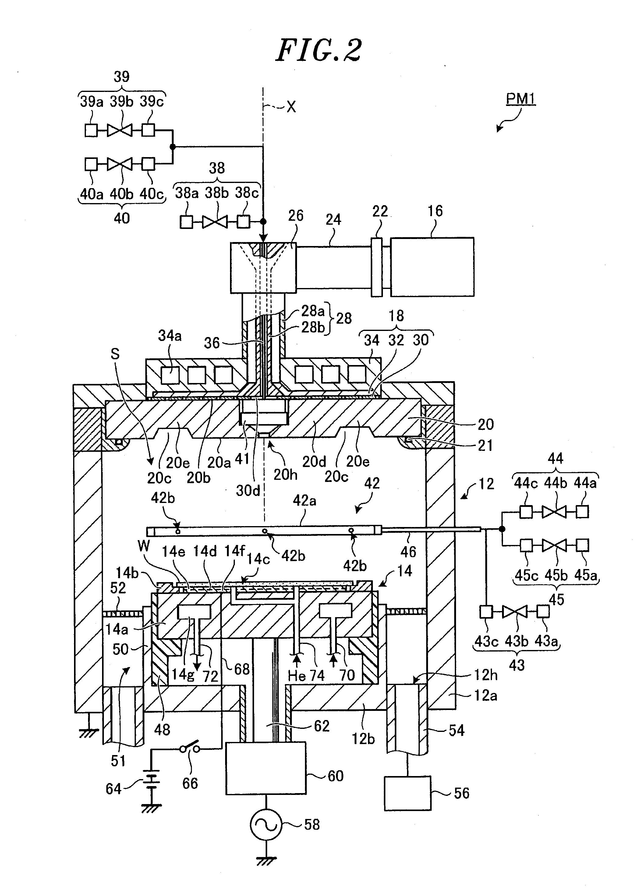
TECHNICAL FIELD[0001]Various aspects and embodiments of the present invention relate to a plasma processing device and a plasma processing method.BACKGROUND ART[0002]In a semiconductor manufacturing process, there is widely used a plasma processing device that performs a plasma process for the purpose of depositing or etching a thin film. Examples of the plasma processing device include a plasma CVD (Chemical Vapor Deposition) device for performing a thin film deposition process and a plasma etching device for performing an etching process.[0003]The plasma processing device includes a processing chamber for processing a target substrate, a stage on which the target substrate is mounted in the processing chamber, a gas supply system for introducing a processing gas required in a plasma reaction into the processing chamber, and so forth. The plasma processing device further includes a plasma generation mechanism for supplying electromagnetic energy such as microwaves or RF waves into ...

Claims


Application Information

Patent Timeline
Patent Type & Authority Applications(United States)
IPC IPC(8): H01L21/67H01J37/32H01L21/3065
CPCH01L21/67069H01J37/32917H01L21/67248H01L21/3065H01J37/32192H01J37/32238H01J37/32522H01J37/32743H01J37/32935H01L21/02315H01L21/67739
Inventor MATSUMOTO, NAOKITOMITA, YUGO
Owner TOKYO ELECTRON LTD
Learn More