Electrochemical reduction device and method for manufacturing hydride of aromatic hydrocarbon compound or n-containing heterocyclic aromatic compound
a technology electrochemical hydrogenation method, which is applied in the direction of electrolytic organic production, manufacturing tools, electric circuits, etc., can solve the problem of difficult industrial hydrogenation of aromatic hydrocarbon compound benzene rings, and achieve high efficiency
- Summary
- Abstract
- Description
- Claims
- Application Information
AI Technical Summary
Benefits of technology
Problems solved by technology
Method used
Image


Examples
first embodiment
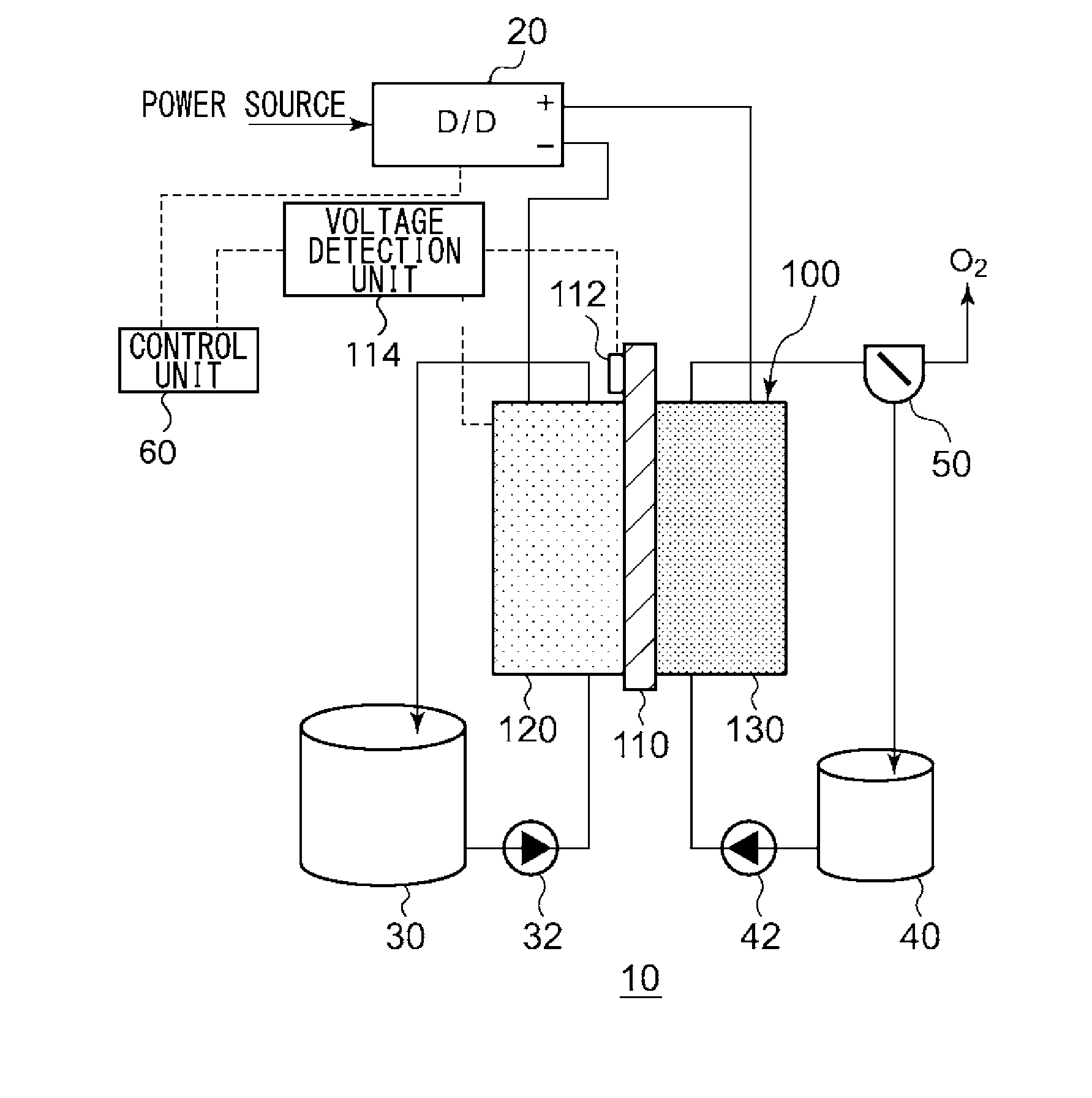
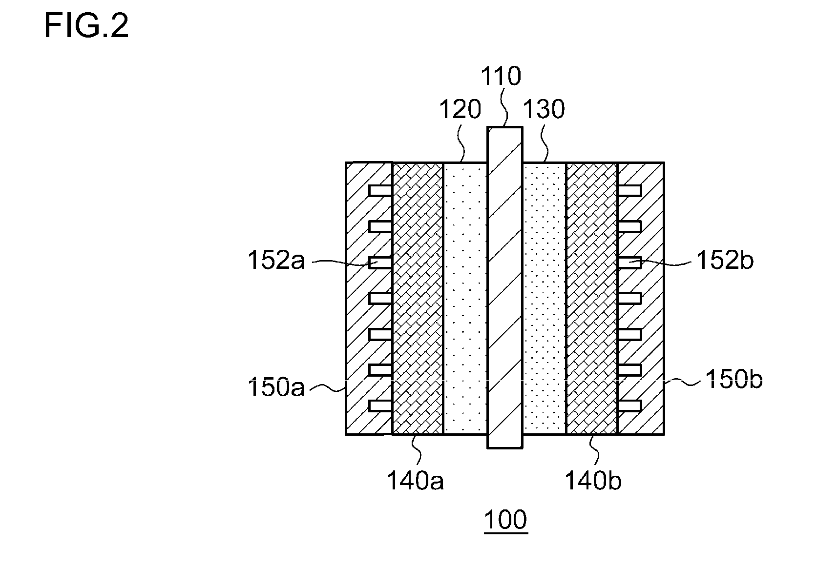
[0025]FIG. 1 is a schematic diagram illustrating the configuration of an electrochemical reduction device 10 according to an embodiment. FIG. 2 is a diagram illustrating the configuration of an electrode unit of the electrochemical reduction device 10 according to the embodiment. As shown in FIG. 1, the electrochemical reduction device 10 has an electrode unit 100, a power control unit 20, an organic material storage tank 30, a water storage tank 40, a gas-liquid separator 50, and a control unit 60.
[0026]The power control unit 20 is, for example, a DC / DC converter for converting the output voltage of a power source into a predetermined voltage. The positive electrode output terminal of the power control unit 20 is connected to the positive electrode of the electrode unit 100. The negative electrode output terminal of the power control unit 20 is connected to the negative electrode of the electrode unit 100. With this, a predetermined voltage is applied between an oxygen evolving ele...
second embodiment
[0074]FIG. 5 is a schematic diagram illustrating the configuration of an electrochemical reduction device according to a second embodiment. As shown in FIG. 5, an electrochemical reduction device 10 comprises an electrode unit assembly 200, a power control unit 20, an organic material storage tank 30, a water storage tank 40, a gas-liquid separator 50, and a control unit 60. The electrode unit assembly 200 has a laminated structure where a plurality of electrode units 100 are connected in series. In the present embodiment, the number N of the electrode units 100 is five. The configuration of each electrode unit 100 is similar to the configuration according to the first embodiment. In FIG. 5, the electrode units 100 are simplified for illustration, and liquid diffusion layers 140a and 140b and separators 150a and 150 are omitted.
[0075]The positive electrode output terminal of the power control unit 20 is connected to the positive electrode terminal of the electrode unit assembly 200....
third embodiment
[0084]FIG. 6 is a schematic diagram illustrating the configuration of an electrochemical reduction device according to a third embodiment. The basic configuration of an electrochemical reduction device 10 according to the present embodiment is similar to the basic configuration according to the second embodiment. In the present embodiment, an electrode unit assembly 200 is held in an electrolytic tank 300. A second circulation pathway is provided between the electrolytic tank 300 and a water storage tank 40, and the electrolytic tank 300 is filled with water supplied from the water storage tank 40. Water that fills the electrolytic tank 300 can circulate in oxygen evolving electrodes 130 of the respective electrode units 100.
[0085]In addition to effects that can be obtained in the second embodiment, the electrochemical reduction device 10 according to the present embodiment has an advantage of decreasing an in-plane temperature difference of the oxygen evolving electrodes 130, a tem...
PUM
| Property | Measurement | Unit |
|---|---|---|
| temperature | aaaaa | aaaaa |
| thickness | aaaaa | aaaaa |
| thickness | aaaaa | aaaaa |
Abstract
Description
Claims
Application Information
 - R&D
- Intellectual Property
- Life Sciences
- Materials
- Tech Scout
- Unparalleled Data Quality
- Higher Quality Content
- 60% Fewer Hallucinations
Browse by: Latest US Patents, China's latest patents, Technical Efficacy Thesaurus, Application Domain, Technology Topic, Popular Technical Reports.
© 2025 PatSnap. All rights reserved.Legal|Privacy policy|Modern Slavery Act Transparency Statement|Sitemap|About US| Contact US: help@patsnap.com